
This is a guide to give you a fundamental understanding of how car tuning in main assembly works. Because this article is not as scientific, this guide may appear to be all over the place so please be understandable.
Contents
Guide to Car Tuning
All credit goes to Ownedpilot!
Part 1: Identify the Purpose of the Car
Just like in real life, all the cars in Main Assembly has a specific purpose. That purpose would affect the tuning of a car greatly. The tuning on a race car is different from that of a luxury sedan simply because they have different purpose. Therefore, before tuning a vehicle, the purpose of the vehicle must be clearly identified to establish a target driving dynamic . Should it be understeer or oversteer? Should it feel stiff or soft? Should it be fast or slow? How many lateral G should the car pull? How sensitive is the brake of the car? All these questions means that there is no correct answer for how a car should be tuned. And it is impossible to please everyone since people may understand the purpose of the car differently.
So what is this guide for? This guide is designed to help players to understand how Main Assembly car physics works and what each parameter would do to a vehicle. But in the end, the purpose determines a car’s driving dynamics and not every car should drive the same.
Part 2: Motors and Wheels
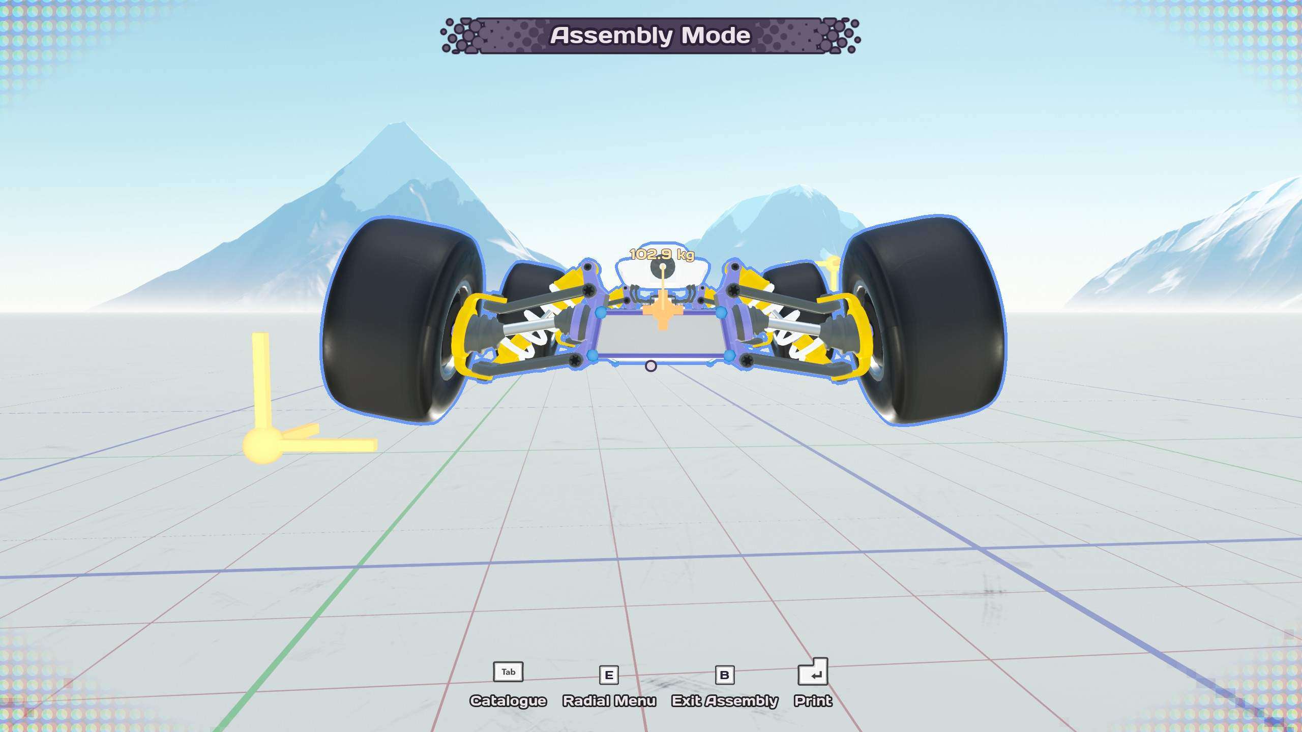
Due to some weird design choices, when wheels are directly attached to the engine part that combines suspension, steering and power, the wheels get more grip and runs smoother. Therefore, for a race car build, custom suspension that uses motor part is not recommended due to the lack of grip. However, for a large scale off-road car, custom suspension may be preferable since it grants a lot more suspension travel. Furthermore, it is recommended to use the engine part to power the wheels to further smooth the ride.
Before selecting the engine, the wheels should be selected first since it would determine the scale of your car. The bigger the wheel, the heavier it is. The harder it is to accelerate. At the same time, it handles bumps better. It is more stable to simulate due to slower rotation speed. In my opinion, the best wheel size is the medium wheels since they have the best of both worlds. But sometimes small wheels are preferable due to their sheer speed. Large wheels are rarely used due to their weight and difficulty to accelerate.
The selection of wheel type is very intuitive since it is attached the purpose of the car. I would therefore not elaborate on this simple topic.
For engine style choice, the normal engine and compact engine are physically identical and therefore the compact engine is usually the default choice due to its cooler look and smaller profile. For engine size choice, unless the scale of the car calls for small engine, large engines are usually the default choice for various benefits. The first benefit of using large engine is obviously power. The second benefit of using large engine is strong brakes. The third and usually ignored benefit is the large suspension travel. With large suspension travel, a softer suspension setup can be used which would improve the mechanical grip of the car. In addition, one trick that can improve the handling of aero grip heavy car would be more viable. This trick would be covered in the later sections.
Part 3: Simple Programming Tuning
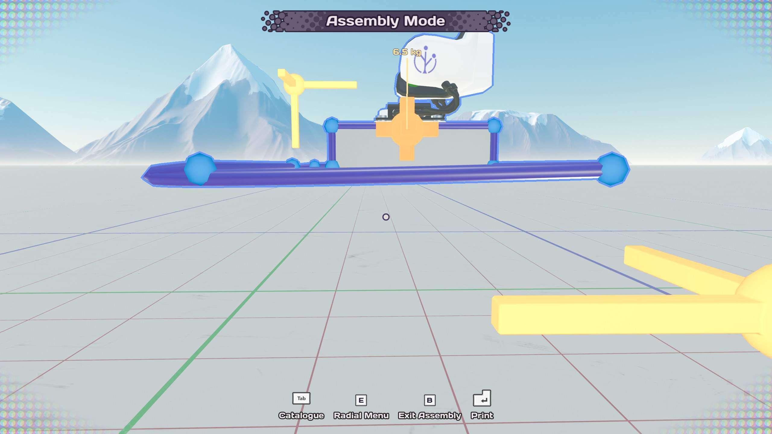
After choosing wheel size and engine, the car must be fully built to before tuning due to potential change in weight distribution. The engine must be placed on the center of a rectangular plate for easy tuning later. A speedometer should also be installed to simplify the tuning process. With the car built, start the tuning by opening up the programming panel.
Engine Tuning
The very first thing that can immediately make tuning a lot easier is to separate the programming node of front engine and rear engine. This allows the front wheel and rear wheel to have different settings which is very important to address some problems in driving dynamics. After clicking on the programming node, this is the menu the game provides to tune the performance of the engine part.
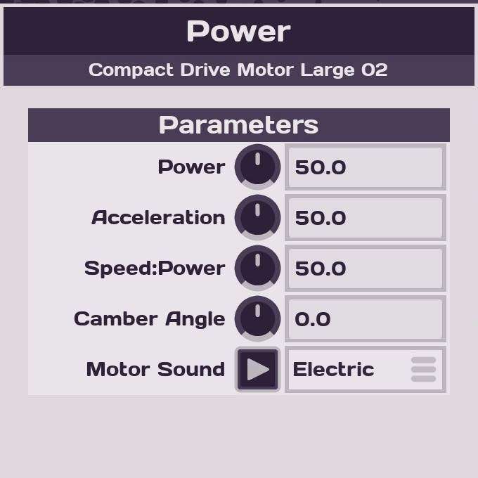
Power and acceleration are self explanatory. A key note about acceleration is that it is very hard to spin the tire in Main Assembly, therefore, setting acceleration and power to 100 does not guarantee an uncontrollable car. However, if a car has a very short wheelbase and a horrible weight distribution, wheelie may be a hazard that must be monitored by limiting the acceleration of the engine.
Speed:Power ratio is usually what most new players have problems with. As explained in by the dev, lowering this number grants higher top speed but lower torque, increasing this number gives higher torque but lower top speed. Each build has their own best ratio value due to the difference in design, but each wheel size and engine combination has a universal starting value for tuning. Due to my lack of experience in smaller engine sizes, I would only provide value for large engines. For large engine and small wheel, the starting value should be around 15. For large engine and medium wheel, the starting value should be around 30. For large engine and large wheel, the starting value should be around 40.
As mentioned in the previous paragraph, these recommended values are only the starting point. To get the desired speed: power ratio value, the first step is to turn on the advanced mode of programming page and hook a debug node to the speedometer. Because the speedometer output speed in m/s, set the multiplier in the debug node to 3.6 for km/h or 2.2369 for mph. It is also highly recommended to put the units in to avoid confusion. Then do some top speed run on the flatland to fine tune the speed: power ratio to the desired value.
As the speed of the car increases, power understeer may become severe (understeer means the car won’t turn). A simple remedy to this is to decrease the speed: power ratio of the front engine only. This decrease the torque of the front engine and allow the front wheel to have a firmer grip. Just like the tuning of Speed:Power ratio, I would also provide value only for large engines. For large engine and small wheel, the starting value should be around 3. For large engine and medium wheel, the starting value should be around 10. For large engine and large wheel, the starting value should be around 30.
Camber angle is exactly what it says. A positive camber angle would let the top of the wheel to lean outward. A negative camber angle would let the top of the wheel to lean inward. Although this value is tuned in the programming, the tuning of this parameter would be covered later in the tuning of suspension parameters.
Steering Tuning
For a better driving dynamics, it is recommended to implement a speed sensitive steering to lessen the understeer problem and make the car more agile at lower speeds. This can be easily done by dividing the steer input with the speed form speedometer and then multiply the resulting value with a constant. Then change the steering angle of the front wheel to 45 degrees. The starting value of this constant should be 15. For a more aggressive steering, increase the constant value and vice versa. Keep tuning this value until the car steers with the most amount of steering.
Brake Balance
Similar to engine power tuning, the programming node for front engine braking and rear engine braking should also be separated to adjust the brake balance. To start the brake balance tuning for large engine, the front brake usually have a brake power of 100 while the rear brake usually have a brake power of 20. Increase the brake power of the rear would make the car oversteer when braking and turning. Decrease the brake power of the rear would make the car understeer when braking and turning. Although a starting value is provided, a lot of driving test is required to get the best brake balance. For me, I usually test the car on the first corner of Monaco GP track I had built to find the best brake balance.
Part 4: Suspension Setup
Unlike the previous section, there is no good starting value for suspension setup. Therefore, the only way to get a good suspension setup is rigorous test driving which can take a lot of time. Also, some of the setup involves changing the geometry of the plate where the engine is mounted to. Given the complexity of this topic, I would try to simplify as much as possible and adhere to Main Assembly physics.
Stiffness and Damping
Some updates ago, the devs enabled the capability to adjust the stiffness and damping of the engine part which opens up a lot more options for car builders. To access the stiffness and damping of the engine, simply highlight the engine part by clicking it. After the acceleration slider pop up, simply press T to cycle to stiffness and damping.
As has mentioned, each car has its own set of best stiffness and damping value. But there are some guidelines to follow to help find the best value.
- Rear suspension should be slightly stiffer than the front suspension to handle bumps better and car rolling better.
- Soft suspension makes the car handles sluggish, rolls more when turning but handles bumps better. Hard suspension makes the car handles sharp, rolls less when turning but handles bumps worse. Sometimes, allowing the car to roll when turning may improve the mechanical grip.
- Damping eliminates the vibration of the car when it hits the bumps. Increase damping when car vibrates too much after hitting a bump or finish turning.
Anti Roll and Camber
For normal off-road vehicles, car rolling may be necessary to eliminate bumps. Thus, the normal vertical mount should be sufficient. Unfortunately, for high speed racing, rolling may be harmful and anti-roll bar is not available for engine part. But there is a technique for handling the excessive roll:
With this method, the suspension would be stiffer when the car is rolling and softer for normal up and down motion. However, the wheel now has too much negative camber which need to be corrected by introducing positive camber in the programming to straighten up the wheel.
The amount of positive camber is determined by the desired camber relative to the ground. For wheels in Main Assembly, camber angle of +- 2 degrees is usually the maximum or the wheel may lose grip. Here are some general effect of camber angles:
- Increasing positive camber increases stability and improves the off-road capability of the vehicle but hinders the cornering capability.
- Increasing negative camber increases lateral grip but reduces longitudinal grip. Too much negative camber may result in decreased acceleration and increased braking distance.
- Usually the rear wheel should have more negative camber than the front wheel to provide stability but the different weight distribution of the vehicle may result in different setup.
Rake and Toe Angle
If the car has some aerodynamics parts, it is important to consider rake of the vehicle since it can greatly affect the aerodynamic performance of the vehicle. Rake stands for the amount of height the rear is raised relative to the front. Increasing the rake would improve the stability of the aerodynamic of the car and shift the aerodynamic center forward. However, too much rake would introduce excessive amount of drag. Fine tuning rake can greatly enhance the performance of a car that has aerodynamic parts. This is why mounting the engine on the center of a rectangular plate helps with this part of tuning. Instead of moving the plate up and down, the rake can be fine tuned by bending the frame forming the rectangle. A rule of thumb for any car that has aerodynamic is that it is important to keep some rake to make sure the car does not take off like Mercedes-Benz SLR when hitting the bumps.
Toe angle refer to the angle the wheel points toward or away form the center of the car when viewed from above. Toe-in or positive toe means that the wheels points toward the center when viewed from above. Toe-out or negative toe means that the wheels points toward the center when viewed from above. Usually, increasing the toe angle would reduce top speed and an incorrect toe angle may make the car hard to drive. Therefore, when unsure, a zero toe angle is usually fine for cars in Main Assembly. Only adjust toe when the car is severely understeer no matter what or the car is not stable for high speed.
Although toe angle can be adjusted using steering, it is usually not recommended and may lead to issues when handling the bumps. Adjusting the plate where the engine is mounted on is a more stable option. If the anti roll installation was already applied, the toe adjustment can easily achieved by twisting the front frame or the rear frame of the mounting plate a bit up or down. In short, there must be a difference between the center height of the two frames to give toe angle. If the front frame has a center higher than the rear frame, the wheels would have tow-out. If the front frame has a center lower than the rear frame, the wheels would have tow-in. For different kinds of power distribution, the toe angle would do different things. Here is a list of what each toe angle would do to different axis and different power distribution settings:
- For front wheels, toe-out would increase stability when applying power but decrease stability when braking and turning without power. Toe-in would have the exact opposite effects.
- For rear wheels, toe-in would increase stability when applying power but decrease stability when braking and turning without power. Toe-out would have the exact opposite effects.
And still, the best toe setting can only be found by rigorous test driving.
Caster Angle and Ackerman Steering
Caster angle is the angle of the steering axis relative to the ground. This angle would determine how strong the steering would return to the center. However, because the steering in Main Assembly is controlled electronically, this tuning is not necessary.
As for Ackerman Steering, it is a mechanism used to reduce the amount of wheel scrubbing by letting the outer wheel steer less than the inner wheel when turning. As already mentioned, because the steering is electronically controlled, it is possible to implement this kind of steering mechanism via programming. Unfortunately, I do not have authority on this topic since I rarely implement this mechanism in my own build. However, I do know that increasing Ackerman would improve the car’s ability to handle low speed corners but decrease the stability in high speed corners. The Anti-Ackerman would do the opposite. Therefore, for optimum performance (if necessary), implementing an adaptive Ackerman steering may be necessary. Otherwise, zero Ackerman angle should already be enough if implementing this mechanism would complicate programming.
Part 5: Electronic Assistance (ABS and TCS)
For both ABS and TCS, only the principle of how they work will be covered. The reason for this approach is to not limit players to a certain algorithm and allows player to come up algorithms of their own. And quite surprisingly, the principle of how they work are quite similar.
One crucial part of ABS and TCS is wheel speed. To calculate wheel speed, first we grab programming node that outputs the rotation speed from the engine part in the programming. The unit the rotation speed outputs is rotations per second. We can then multiply this number with pi and the diameter of the wheel to get the wheel speed. By comparing the wheel speed and the real speed measured by speedometer, we can proceed to regulate the brake power and engine power input to reduce wheel spinning and brake locking. For ABS, reduce brake input when the wheel speed is lower than real speed. For TCS, reduce power input when the wheel speed is higher than brake input. One key note for ABS and TCS is that some level of wheel spin should be allowed to get the most out of the wheel. Tuning that wheel spin level is a part of tuning ABS and TCS.
With advanced mode enabled, torque vectoring and brake vectoring is also achievable by adding a gyroscope. By monitoring the rotation speed of the vehicle using gyroscope, it is possible to calculate the speed on each side of the car. Then by using mirror mode on the engine part (red is right, blue is left and I might be wrong). It is possible to limit the power input and braking input of a single side of the car. This allows the speed:power ratio of the front wheels to be the same as the speed: power value of the rear wheels without having to worry about understeer.
Most of my performance car builds now feature torque vectoring TCS but I rarely implement ABS. Some of my older builds actually feature ABS but I stopped using them due to a weird bug that may break ABS: brake bug.
Part 6: Bugs and Tricks
Brake Bug
This is a very dangerous bug which require great cautions to use. It turns out when the brake input is low (around 0.2), the engine would first accelerate very quickly before slowing down. When using ABS, there is a risk that the car may be sent into a wall because of this bug. As the player who first discovered and reported this bug to the community, I also found a way to take advantage of this bug. I first see if I can keep the wheel spinning at ridiculous speed by using a controller to tap brake lightly. After I see the drastic increase in speed, I proceed to automate the process with programming. Here is an example of a car I actively used brake bug to achieve high speed:
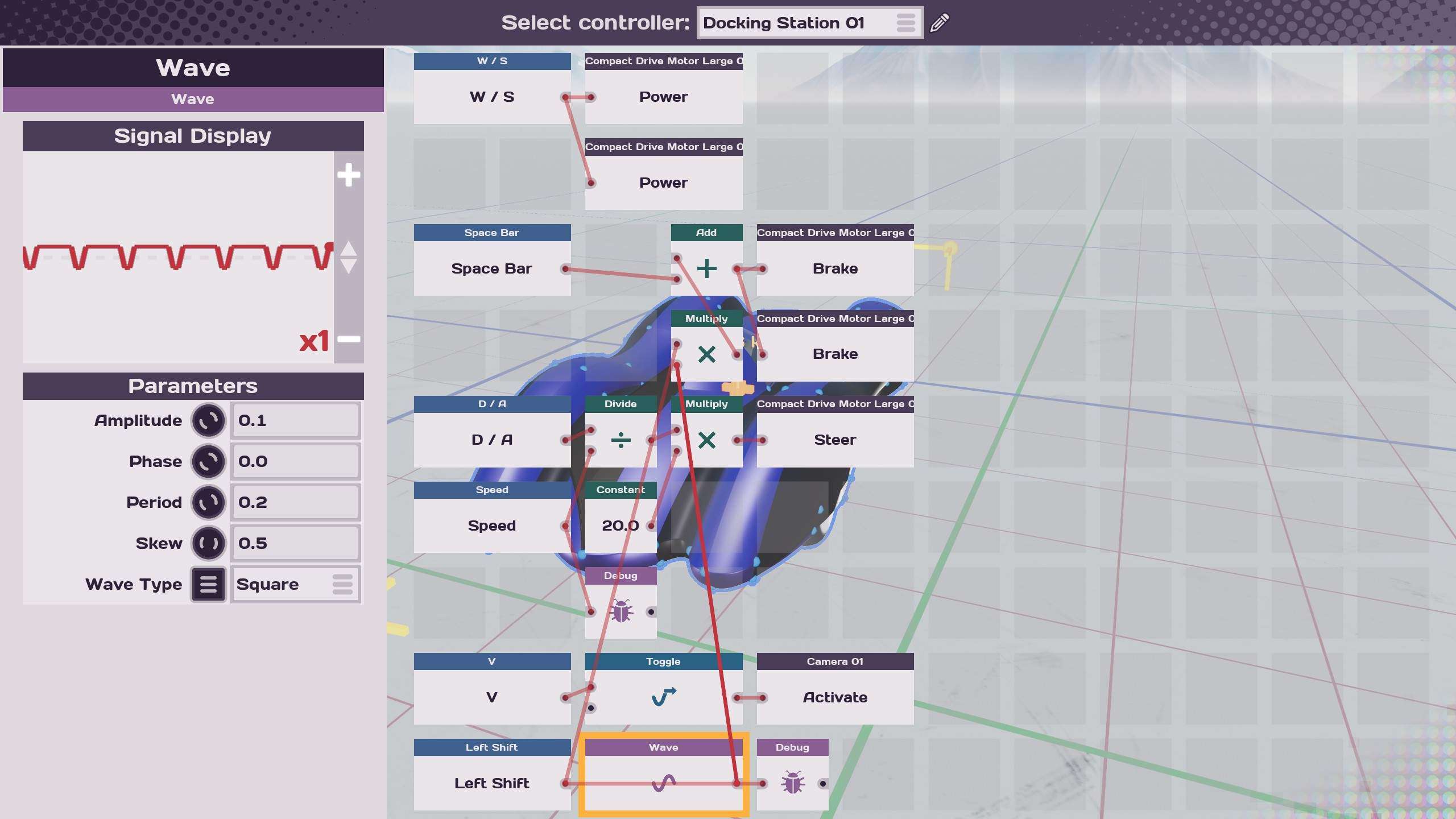
This is the 1936 LMC Pegasus Salt Runner created by Jerry Heartland and me who added the brake bug. By setting the wave function to have the period and skew demonstrated in the picture and adjusting the magnitude based on the braking value of the engine, it is possible to force the engine to spin at its top speed. This bug allows a lower speed: power setting of the engine to be used which means a higher top speed. In this example, the car is capable of top speed of 320km/h.
However, just like real life engineering, nothing is free. By forcing the engine to spin at a speed higher than what devs intended, the simulation stability also suffers because of it. This means if the speed: power setting gets too low, it is possible to send the car into an uncontrollable state. This effect is extremely severe when using small and medium wheels. Therefore, there is a minimum speed: power value before the wheels go flying and that value can only be found test drives. For large wheel cars, using this bug is necessary to accelerate the car fast enough to compete with smaller cars. Due to the great stability of large wheels, the engine would still behave normally except for the extra power. To get the most out of this bug, the speed: power ratio would have to be re-tuned using the similar process introduced earlier to achieve a good balance between top speed and acceleration.
Add Weight to Wheels
One of the most annoying part of Main Assembly physics is the wheel physics simulation. I have mentioned multiple times on discord server but the devs haven’t laid out a plan to fix it yet. Therefore, the wheel bounce is what we have to live with. The wheel bounce is the most noticable when using small wheels and medium wheels. One way to combat this effect is to add 1kg weight to the wheels. This would reduce the wheel bounce somewhat and lead to a better driving dynamics. Due to the large mass of the large wheel, no mass is necessary to combat the wheel bounce.
Bug Aero
Due to the lower speed of the car, a realistic looking aero device usually have very little effect on the grip of the car. But there is a trick to improve the aerodynamic efficiency of the aerodynamic devices on the car which I call bug aero.
When calculating the aerodynamic effect of a plate, the game would take both its angle of attack and curvature into consideration. When the curvature of a plate is high, the aerodynamic effect of the plate would also be high. A certain combination of angle of attack and curvature would result in wings that can produce negative drag or thrust. This effect was first discovered and documented by Leiywen and further exploited by me. To get a lifting surface with incredible lift to drag ratio, the lifting surface must have a cross-section like this:
Although the plate is nearly flat, it is not completely flat. That little bulge insures that the lift is pointing downward, creating downforce. Similarly, by flipping the bulge, it is possible to turn the lift upward and create the most efficient wing. This is the cross section profile I use for my helicopter blades.
By scattering these aerodynamic surfaces around the car, it is possible to create insane downforce without creating too much drag. However, too much abuse of these surfaces may lead to unrealistic handling and hard to tune cars so do be aware.
Aerodynamic balancing
However, if a car has horrible aerodynamic balance, it may still end up driving horribly. An easy way to check aerodynamic balance is to drop the car from incredible heights. If the car drops straight down without any tendency to pitch up or down, the aerodynamic balance is usually fine.


Be the first to comment