Guide to Advanced Water Wheel Arrays
It is possible to build looping water arrays that generate tremendous amounts of power!
First let’s discuss the concept of a looping water array in steps:
- Source water is fed into mechanical pumps.
- Mechanical pumps dump into a channel to concentrate the flow.
- The flow is pushed through water wheels causing the level to drop – the zig zag helps speed.
- The height of the channel is adjusted to accommodate.
- Water flows out and down into the input channel.
Each loop adds the outflow to the CMS until it reaches the max the pumps can do!
Flow Limitations
To the best of my experimental knowledge the cross sectional flow within a channel is limited to approximately 2.5 CMS which means a 2 wide 1 deep channel can hold 5 CMS, a 2 wide 2 deep can hold 10 CMS, a 2 wide 3 deep can hold 15 CMS, and a 2 wide 4 deep can hold 20 CMS

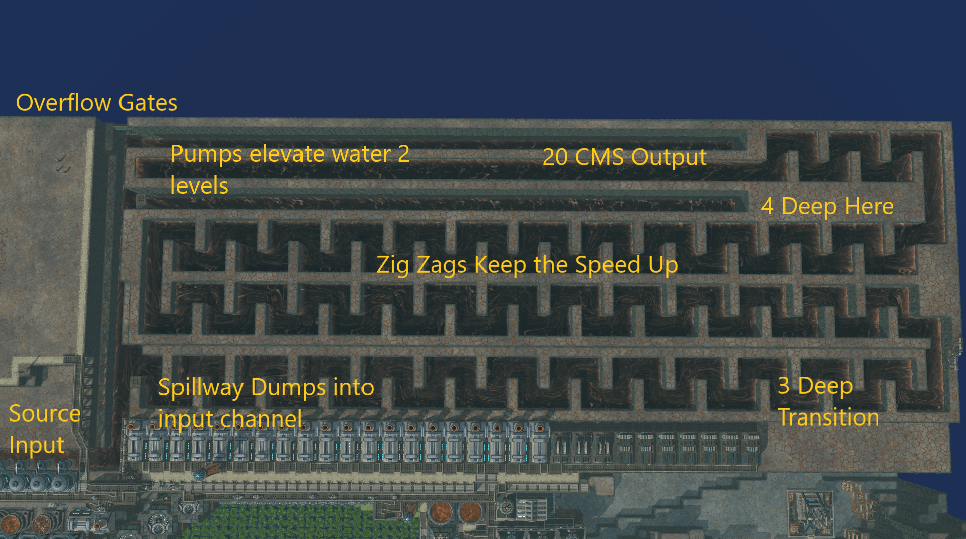
Raw Land Geometry Annotated
Some Key details here
The input channel is at -6 height the output channel is at -4 height relative to the top of the array this ensures downflow through the system. The outflow location is set up to dump all CMS that has made it through the channel.
The Zig Zag speeds up water symmetrically and ensures the flow keeps moving.
The upper level drops late in the system in order to ensure water is interacting with the wheels.
Further drops are possible – geometry limited this build.
The output through the gates only occurs once the system is fully charged.

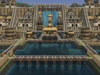
Assembled Array 124K HP – my personal record for this # of wheels!
Some Key details here
- External Power is required to boot up the array and it can take a while to charge up fully while the water in the system builds up.
- This arrangement of wheels eliminates internal power transfer poles.
- Geometry limited the size of this build.
- Evaporation may be the key limiter here.


Be the first to comment