
This guide aiming to give pointers how to design effective engines for most situations!
Guide to Designing Engine
This information continues from another guide about gearboxes.
You don’t necessarily need to read that guide if you already know how gearboxes operate or if you don’t want a detailed explanation. I will try to avoid repeating information that was already discussed there, including the section on basic engine information.
Engines are a necessary component for almost all vehicle designs in Stormworks. We are focusing on the advanced game mode, because in that mode, a significant portion of a vehicle’s weight needs to be engines for it to move.
This guide assumes you already know the fundamental steps of assembling an engine. This includes connecting air, coolant, fuel, exhaust, and power. It also assumes you understand the basic functions of gearbox, clutch, and generator components.
Introduction to Engines
We will not be covering jet engines in this section because how they fundamentally work very differently compared to the others. They may have their own section in the future.
There are fundamentally 3 different kinds of engines, an oversight is given below:
Pure combustion engine

They come in 3 different sizes: Small, large, and “oh god why”. The main differences between the 3 different sizes are 3: How you hook them up, their “sweet spot”(discussed later) and torque values.
Every engine can provide the same amount of RPS, although i have a distinct feeling this will change in the near future. Despite what may be apparent from this guide’s length, the way the engines work is really simple.
Pros:
- Electricity drain is minimal.
- Does not require a generator/alternator, and if desired can take only a fraction of engine performance.
- The engine’s performance is easy to predict in most cases.
- Fairly simple to set up.
- (Very) Lightweight in light setups.
Cons:
- Most fuel draw on all of the engine types.
- Most volatile to design mistakes.
- Grows heavy when you need a huge amount of power due to literal tons of fuel.
- Prone to stalling.
Hybrid / Electric assist drive
These are 2 drives that are fundamentally different, but they function so similarly i put them in the same category.
A hybrid drive toggles between electric drive being active with high battery, and disengages the electric drive at low battery to allow the battery to recharge and turns on the fuel engine. The aim is reduced fuel consumption.
A supplemental electric motor works with the engine all the time to increase its power. This is one way to have a strong engine that is also physically small. This setup often uses more fuel, but with careful adjustments, the fuel consumption can be similar to not having the electric assist.
Pros:
- Technically is immune to stalling (Electric Assist / Electric mode only).
- Has high electric power generation.
- Can punch far beyond its size category in torque (Electric Assist).
- Very low fuel consumption (Hybrid drive).
- Relatively simple setup (Electric assist).
- Scales better to rising tonnage of vehicle.
Cons:
- Vulnerable to battery running out (as well as being struck by lightning).
- More complex design than conventional combustion engines (especially Hybrid).
- Excessively heavy in light vehicles (Hybrid drive especially).
- Heavy weight of many batteries (can be neutral in cases where batteries can be utilized as ballast).
Pure electric drive with diesel generator
(Example only for illustration, doesn’t actually work as simply as this)
A setup common in very large freighters, as well as some newer electric cars as a backup generator. It utilizes usually larger engines to produce electric power, which is then displaced and used elsewhere.
Pros:
- Very low fuel consumption when optimized.
- Easy to optimize engine(s) to provide generators as needed.
- Allows having engine and fuel where-ever you want while propulsion only needing a small amount of space.
- Absolutely incapable of stalling.
- Relatively simple setup.
Cons:
- Overwhelmingly heavy compared to other options.
- Needs even more batteries, making it even heavier.
Combustion Fundamentals (Simple Factors)
I will keep this section as data only, there’s a few fundamental things on how diesel engines work in this game.
All these will be using combustion engines, so refer back here if you’re confused on some design decisions.
Heat
- The rate that the engine heats up with is tied directly to its RPS value.
- We can reduce heat by pumping liquid (preferably water) through it.
- We can increase this heat reduction by pumping more liquid through it.
Output
- The torque output in the engine rises with the RPS.
- The RPS is variable, but can further be modified by a gearbox.
- The engine’s maximum possible RPS drops based on the load forced onto the engine.
- Making the engine only partially engage via clutch reduces the load and allows higher RPS.
Fuel
- The engine doesn’t consume fuel based on load.
- The engine consumes fuel based on RPS; more RPS, higher consumption.
Exhaust
Seemingly matters very little, so long it can be freely output, it can only be properly measured by looking at the engine for whether or not there is enough exhaust output. Visually, you will get thicker plumes of smoke unless you direct it through more exhaust pipes.
Air
Requires more air for more RPS on the engine, but has no real issue sucking up incredible amounts of air without any kind of compressor
Using this checklist and only this checklist, we can design all types and kinds of engines.
Designing a Boat Engine (Combustion Only)
Dude, what if we exploded a dinosaur to make a boat go forward?!
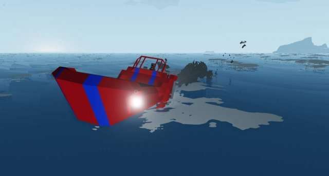
We’re going to be using this old, gutted speedboat design of mine. It’s an old dog, made around version 0.4, which would be around the rocking 80’s in game development terms, that’s why it has such a silly name and color scheme!
This is a build-along, so load up Stormworks and let’s start going!
The dreaded theory section (that’s actually short)
“The general who loses a battle makes but a few calculations beforehand. “ Sun Tzu, The Art of War
Yes, i’m dropping Sun Tzu’s wisdom on you (and padding this to make it look longer than it is).
We will be dealing with a load (what the engine is working). The propeller is at its heaviest when in the water, and can only give propulsion in it, the drag of the body is the only notable thing that’s preventing the propeller from turning. We can determine from this that we’re dealing with a constant load (outside of planing!).
- This, effectively means that we are perfectly fine with having one gear.
- We have literally infinite coolant. We don’t need coolant tanks, we can use seawater directly
The second theory section
The whatnow?
Well, we’re making a boat with a specific design, so let’s consider the part of how a boat works on water, and more specifically, how this boat works on water.
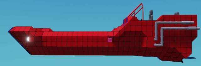
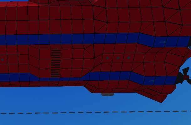
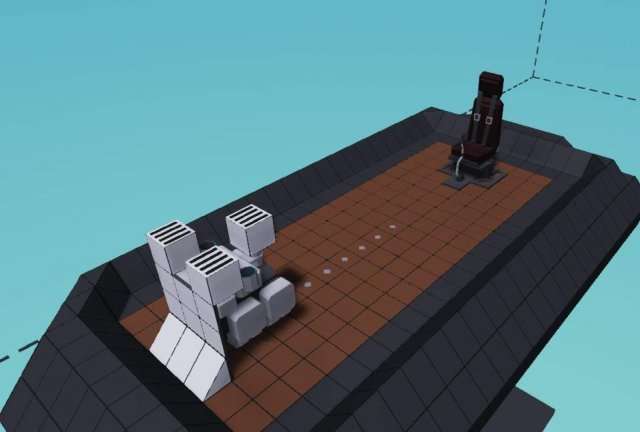
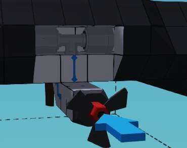
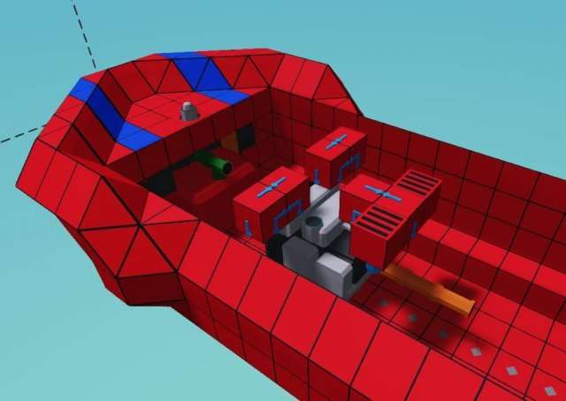
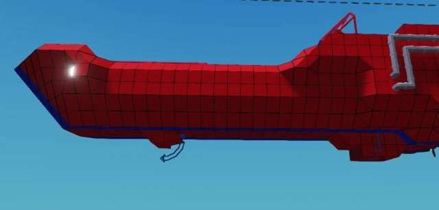
This is what the boat looks from the side, we can see the pair of props to the right, the center of mass in pink (i’ve added engines already), and that’s all we need to know. Let me apply some MS paint to the image.

The center of mass works like the fulcrum (the middle point of a lever) in a see-saw. Our center of thrust (blue arrow) is below the center of mass, which causes the nose to lift up(light purple arrow). This is something that’s desirable in a speedboat, but it is not desirable otherwise. The bow will also want to lift itself off of the water because the water has more resistance to motion (drag) than air, which also causes lift.
In large commercial vehicles the props are often angled so they don’t provide upward bow lift like this. In boats, we generally want most of the weight toward the front to reduce this lift, which makes it far more controllable and easier to handle.
I’m all theoried out, what now?
The theory is simply for learning how to think about these little design challenges, some people can wing it, others need to think about it. Generally being able to wing a design comes with practice.
The boat comes with premade hull and cockpit, fuel tank, and exhaust system. Everything else, we’re going to make.
Now, we build some stuff
Building some stuff
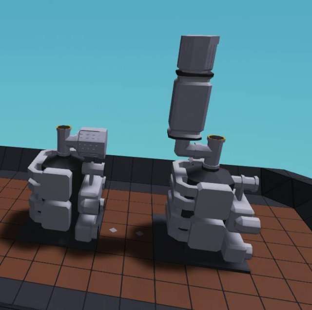
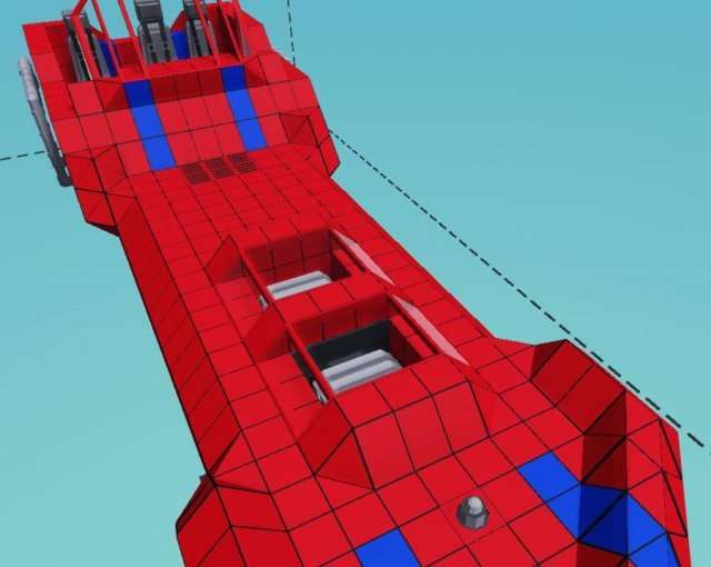
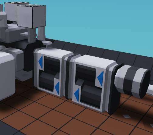
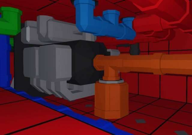
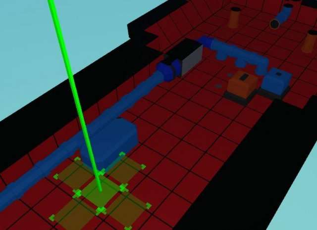
We’re going to need 2 engines. Place them toward the front. How you place them is your own call, and where you place them is your own call. This is how i placed mine. If you place your engines this way, make sure to mirror (U) one of the engines so the pipes are on the same side.
Let’s hook up the cooling now, since we’re operating a boat, we have an ocean-sized cooling tank.

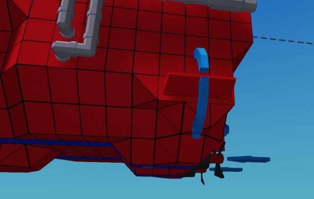
I made a small extension to the bottom of the boat for sucking up water. It’s effective enough with its current alignment and doesn’t really need anything extra, it’ll happily suck up all the seawater running against it. You can also lay the inputs flush against the bottom, but a bulge like this adds more drag which makes it harder for that part of the boat to lift off the water, and gives more area for it to suck up cooling seawater. You could have a pump here, but it’s not exactly necessary.
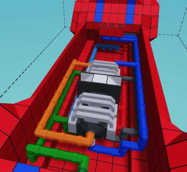
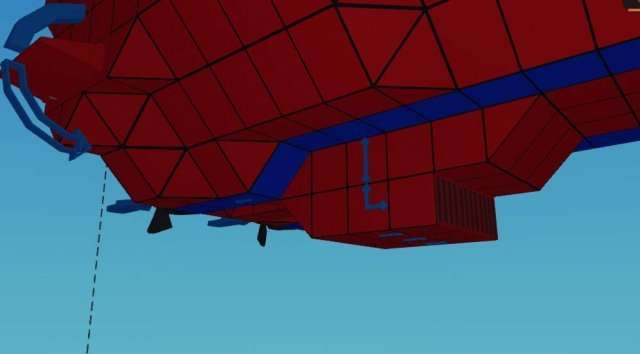
For getting rid of the hot coolant, i just put a couple of fluid ports directly below the ladder on the back and piped my way over there, my internals now look like this. Color coding pipes is good for sorting them out later, you should do it!
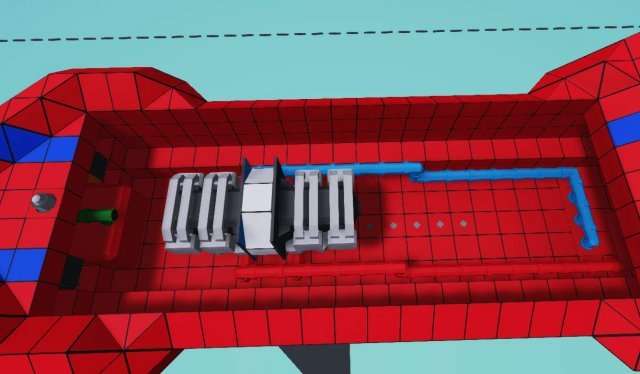
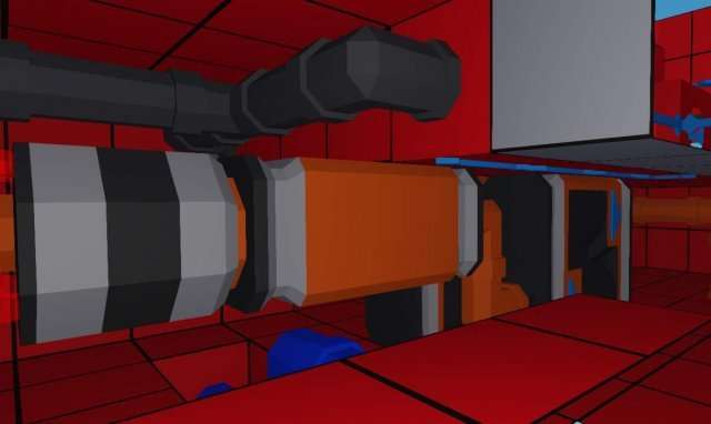
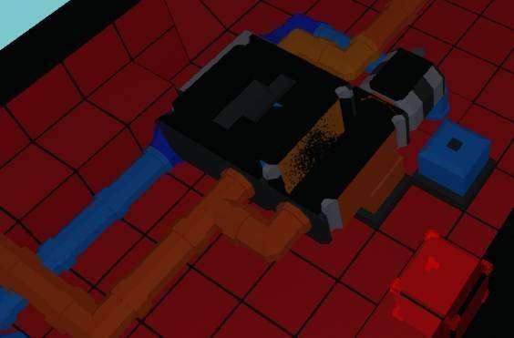
This is what a fully hooked up (except for power) engine looks like. I opted to have equal hookup for the engines instead of one per prop, there are upsides (losing one engine still allows you to go straight just fine) and downsides (can’t engine steer, slightly lower performance with turns) with this kind of design, but it’s easier from a pipe management perspective, even though there’s plenty of space.
Now since this is an engine design guide, and not boat beauty design guide (patent pending) i won’t walk you through hooking up fuel, air and exhaust, just make sure the air intake gets air. How they’re hooked up and designed are up to you, you can even increase the amount of fuel if it does (but for now i recommend you leave those other tanks empty, as they shift the weight a lot).
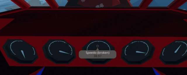
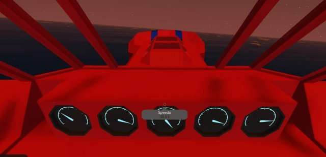
Now hook up the engines directly to the props (this is for testing purposes), then do all the necessary electronics and finally build a cover for the craft without leaving any gaps so this thing can actually float. You’ll find the ignition button pre-installed, just hook up throttle to w/s or install a throttle lever as you wish. The speedo on this thing is broken (because it’s old), you can install a proper speedometer or just go by how it feels. We’ll be doing the tuning after we have a test run!
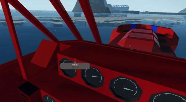
You should at least hook up these:
- RPS.
- Heat.
- Fuel.
Test results
So, we probably agree on these test results:
- The thing is fast as hell, and about as mad.
- Trying to turn at full speed causes disasters to happen.
- The thing hits full RPS, and chews through fuel.
- It eventually blows up due to insane engine stress.
- The boat planes too hard.
Dealing with the test results
Let’s address the positives:
- It’s fast for a normal prop driven speedboat, this is desirable.
- It looks rad.
That’s the positives, all of them. We probably want to attack how the engines work, limiting their RPS is one way, but since loading them down doesn’t cause more fuel usage, the better way, in my opinion, is to put in a gearbox with high gearing that forces the engines to run at lower RPS. We’d want to do this anyway to get a reverse gear.
Install one gearbox, and gear it at 1:3 (note which way you’re installing it), then take it for another test-run. The goal is to repeat the test run with different gearings until your engines sit around at 8 RPS, which is the desirable sweetspot for small engines. Since our engines are both tied to the same driveshaft, we can get away by just watching one’s stats.
Deliberating
With the 1:3 gearbox you should notice that we reach about half the RPS that we want, so naturally you’d think we need half the gearing, right? It’s not quite as simple as that, as these things work on a curve. Try tuning it down to 1:2 (33% less) to see what the effect is.
With 1:2 gear, you can reach > 10 RPS, which means that we’re actually putting out more power in those props than with 1:1 gearing. I could reach 30m/s speed, but it was extremely uncontrollable. Since there is a gear between these 2 not as desirable outcomes of opposing ends, we can pick that one and take the 5:2 for a ride.
Conclusions

With these designs we have determined a good compromise for a gear and made a pretty decent engine for a relatively decent speedboat. It uses relatively small amount of fuel for rather solid performance, and it’s sort of stable while doing it.
But… we could do better, couldn’t we? We’ll see this craft again.
Designing a Boat Engine (Diesel-Electric)
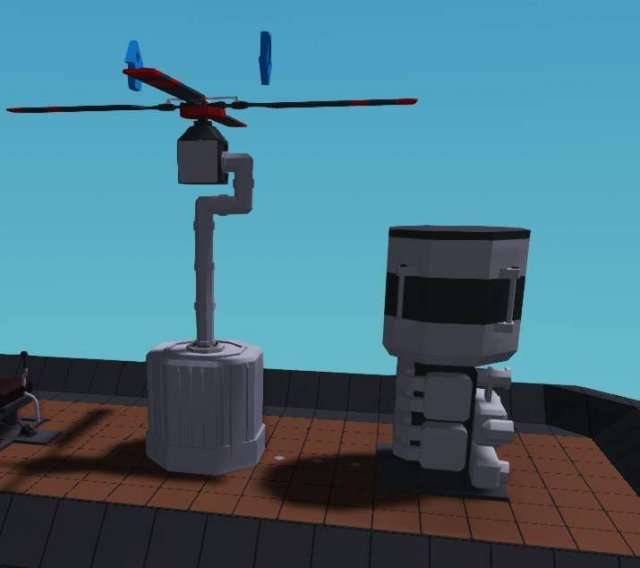
We’re using this sweet dinghy as a basis
We’ll start off right off the bat with a bang. Build an engine as shown and attach fluid ports directly to cooling and air.
Follow it up with an exhaust pipe that doesn’t blow the exhaust in your eyes and a fuel tank.
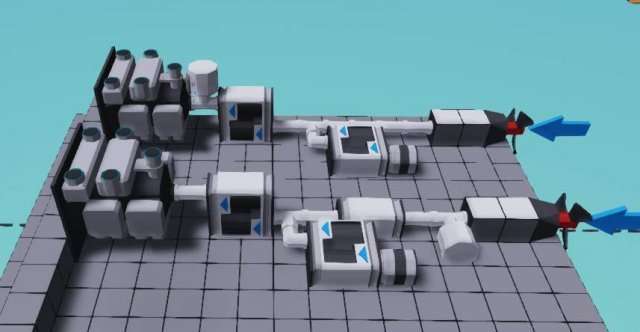
And finally, a pair of gearboxes as shown with a generator stuck on them as shown.
The electric stuff!
Yes, we’re actually done with the engine (or rather, generator) we will tune those gearboxes later.
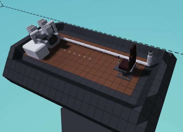
Open up the back of the boat (i’ve colored the insides white for seeing the insides more easily) and install a prop as shown.
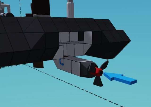
Pipe up from the prop and attach a pair of electric motors as shown.
This is all the space we need for our propulsion. Compared to that monstrosity from before, it’s really compact, isn’t it (apart from the big engine in the front, of course…)? Remember, gearboxes have no positive effect on electric motors!
Make very sure to close off the hole after you’re done completely. The dinghy depends on its flotation ring to stay on the surface. It is not sectioned off at any point, so leaving any points open will turn it into a submarine.
Now wire up the electrics!
Testing time!
Wire up a constant number of 1 to the throttle of the engine, and a starting button.
We’re concerned about 2 things here: Energy production, and energy drain. We should really only concentrate on energy production first.
Here’s the dials (or other readouts) that we want:
- Generator output (Yes, really, one and only).
What we’re looking for
- Highest possible generator output, what else?
I happen to know to get to this figure you need somewhere between 1:7 to 1:9 ratio. You can do some maths, can’t you? For those too lazy to count, 1:3 and 2:5 (or 1:2.5) after each other is 1:2.5*3, or 1:7.5, which is good enough.
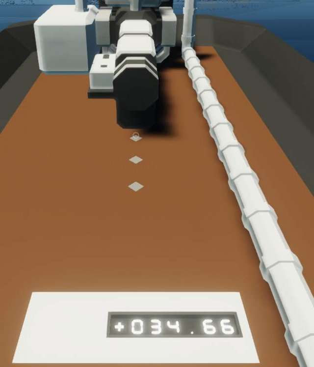
On the left you can see what we’re looking for as a good generator output.
Testing time, round 2!
Round 2? Well, since we’re working 2 systems, we need to test 2 things!
Here’s the dials (or other readouts) that we want:
- Battery (the dinghy comes with a battery multiplier that means we can get % readout on the battery, really useful).
- Fuel capacity (so we can determine how little fuel we’re using).
Now, before we determine what we’re looking for… wire up one of the electric motors directly to the seat, and take it for a ride until your batteries run out to around 80%, then turn on the generator, and keep riding.
What this mini test showed is 3 things:
- Batteries on their own run out really fast.
- The generator puts out more than we need (this is why we have 2 motors).
- The thing uses a neglible amount of fuel.
What we’re looking for
In a system like this you want as close as possible for near 100% (or more, if you’re OK with short pauses here and there in trade of more power output) utilization of the engine’s power generation.
Wire up both of the motors now and take it for a ride.
What this test showed is 2 things:
- It’s way faster without affecting how much fuel is consumed.
- The battery is draining..
Essentially, this means we need to send a portion of the throttle signal to the electric motors. Without a somewhat complex automatic system that adjusts the throttle based on the difference in battery charge decreasing, you can arrive at a reasonable division of throttle output through some informed trial-and-error.
I left my divider microcontroller in the dinghy’s flotation part, and the figure should be tuned to slightly drain the battery while driving around, but also giving it impressive range.
So what have we learned (possibly):
- The engine at the front makes sure the dinghy doesn’t plane.
- Not planing reduces the potential speed, but also makes the ride much more stable.
- Making a generator system is very easy.
- Generators use very little fuel, and it allows practically hiding the propulsion system.
- Batteries without generators run out very quickly.
Designing a Boat Engine (Electric Assist)
So, let’s discuss a little bit on the weirdness of this system.
Electric assist is a little bit difficult to understand as it immediately doesn’t seem to have many benefits, and it’s made even more confounding as there’s multiple ways to set it up. Essentially what’ll happen is that you’re taking some of the engine’s power output to generate electricity, which you’ll then use to force the engine to run at a higher RPS.
It sounds like it shouldn’t work, and it sounds like it should be overunity, but engines have a sweet spot for power output, to sum it up simply, the more you rev up an engine, the more torque it puts out on a curve. The “sweet spot” i keep referring to is different for every engine, for small engines it is around 8, where it doesn’t use too much fuel to put out the power in question. We’re using the electric motor to force the engine to turn, similar to a starter motor.
The secondary benefit is that you also get quite a bit of electricity for your other systems as a necessity for this thing’s function.
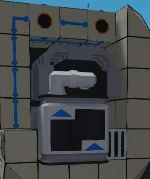
There’s 2 main setups for this kind of engine:
One that’s directly hooked up to the engine (above), this is where the electric motor’s throttle is often limited to curb the hit on the batteries, which reduces how much you need to give to the generator.
One that’s hooked up to the output, where the engine gives half or more of its power (regulated by the clutch between the engine and electric motor), and most of the electric motor is directly tied to the output.
This kind of design is useful in systems where you often need to reverse, so you can just disable the clutch between the engine and the power output, which gives 100% of the engine power to the generator and 100% of the motor to the output, which allows gearbox-less reverse. This can also work as a hybrid system.
We still have some things to think about, but at least it’s only 2 components and their quirks.
Generators: They depend on RPS, giving out more power per rotation put in, but as a downside they also require more torque per rotation as the rotations increase. This wasn’t a thing before, which made it easy to make overunity generators. We need to balance this so we don’t rob too much of engine power just to make electricity.
Motors: They give out significantly more power at higher battery charge… because the electric system in this game is a little bit silly. They give a 100% at 100% battery, and drop out to at an estimate 40% of output at 50% battery, after which they no longer drop down, so we need to keep the battery above 90% at all times, preferrably 95%. This simply means we need more batteries and bigger batteries.
Let’s stop waffling and start building
We’ll be using the same speedboat design as in the very first engine design, so go fetch the workshop link from there if you haven’t already. Our goal is to try to get close to similar performance (!) while only using one small engine.
To try not to repeat myself too much, i won’t be walking you through hooking up the engine again, it’s done in exact the same way as in the combustion section, so hook it up fully without gearboxes or anything special, seal up the top of the speedboat, and take it for a test ride. Besides, there’s enough text in this guide. As before, the design decisions for the intakes and whatnot are completely up to you.

The test results
Let’s have a bit of a moment on thinking about the factors here:
- The speed is good, but it is also a little hard to control.
- The RPS of the engine hits the cap.
- The engine heats up quickly.
- The engine uses up a lot of the fuel.
Let’s attack those issues first by introducing a gearbox. To save on time and effort, a good compromise for a gearbox here is 2:3 ratio, it gets your engine to 9 RPS with a speed of slightly below 10m/s (knowing these values is important for tuning). It for now deals with all the issues and kills the speed, but this is only temporary.
Let’s electrify that boat! Electricity is super effective against water!
We’ll be designing the first system shown on the topmost image of this guide, so make a T-section pipe next to your engine’s power output and slap an electric motor onto it.
It’s a little cramped in here.
Next, we make the gearbox and clutch system leading to the generator behind the currently existing gearbox (since we want as many RPS as possible).
Now let’s wire things up
Put a 1:3 ratio on the generator and hook up the clutch to a throttle lever while hooking up the electricity. The throttle lever is a temporary measure so we can figure out a good clutch ratio for this without making an automated system (which is better, but harder to guide through!).
You also want to halve the throttle of the motor so we’re not using too much energy, so either divide the throttle input by 2 or multiply it by 0.5, your call. This is the same throttle you’re controlling the engine with, so if you’re using w/s, wire it to that.
Test results, round 2!
So… the battery is draining, even with 100% generator clutch, why is that?

Well, we’re actually pushing the engines too hard in this case, so we’re going to have to modify the body a little. Remove the twin props at the back and install a single central one in their place. Now take it for a test run without changing anything else.
Test results, third time’s the charm!
We’ve boosted the engine pretty notably. We reach 12-13 RPS now, and we can reach higher speeds, yet despite this, we don’t seem to be using more fuel than before. The battery drain is still pretty high, and we have to let the engine rev up before we throttle up the generator clutch so that the thing starts generating.
So how do we come up with a solution where we don’t have to screw around with the clutch manually all the time? Let’s try something simple. We know our peak RPS is about 12, so we want a figure that’s around 0.75 clutch (a good compromise that can be found out by testing different values and driving around a while, all while looking at the battery value).
It turns out 12 divided by 16 is 0.75, so we can hook up the RPS of the engine to control the generator clutch, so long we divide the RPS by 15. “But wait, you said…” yeah, that’s the peak of the engine performance. Waves are tossing the boat around and the RPS bounces around so we have to have a little bit of leeway with it, this is just to ensure we have the battery being charged.
Results!
We have managed to get equal performance with the twin combustion engine, despite the setup being more complicated, we’re actually using less fuel and we have energy generation in place, probably enough to even run a floodlight or two permanently.
Even if the engine RPS is probably higher than we want, and we could have even lower fuel consumption, our goal was to hit the performance of the previously designed twin-engine powerboat
This system can also be applied on the twin engine setup to make it even more powerful.
The Boat Designs Extra Credit
No affiliation with that absolutely awful Youtube series.
This section will go above and beyond in showing some tricks (some of which are beyond engine design) that will put some work to make the boats even better.
As the most improvements can be made to the twin engine craft, i’ll deal with that specific craft. As far as the electric drive dinghy goes, the only real improvement that can be done to it is doubling the generator engines and removing the divider.
There are other adjustments possible to this craft, like putting in an electric assist, or separating the engine outputs so that one engine drives one prop, but for sake of brevity i’ll not go into those.
Keep in mind that despite all of these are being done on this single example boat, the methods used here are applicable to most types of boats, the numbers and specifics will differ, but the principle will remain the same.
Deliberation
If you haven’t done it in a while, give the twin engine boat a test run to see how it feels to ride, and determine what could possibly be improved after removing the limiter we put in by dropping the gearing to 1:2. This is the basis of improving the craft, just running around in it and thinking about what could be improved.
- It’s very difficult to turn at high speed without flipping the boat.
- The boat starts planing far too hard at around 11-12 engine RPS.
Those are 2 of the very obvious faults that are the most pressing ones now. Let’s focus on fixing them
Fixing dat stuff
You can imagine this section to be all in Mr. Plinkett’s beautiful voice. If you do not know who Mr. Plinkett is, i will consider you uncultured, but that’s perfectly alright.
Stability improvements
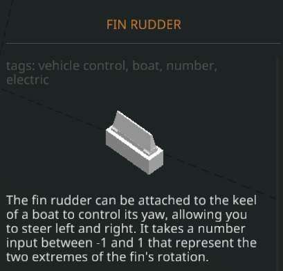
Let me introduce you to one of the most magical pieces in Stormworks. The fin rudder when introduced to water is a drag monstrosity that resists angular motion in an extremely strong fashion, and what’s more, to get use out of it, we don’t even need power for most cases.
All you need to do is install them as shown, you don’t need to hook up electricity or anything, now take it for a test ride. What happened?
Oh, we just doubled the speed. All right then.
Cooling improvements
While the engine without any cooling improvements sits at around 105 degrees on a steady waveless ocean, the problems begin when we start catching air and the engine jumps above 15RPS. Unfortunately this is also where we get most of our speed increase, so we have a dilemma:
Solution 1: the easy way out: Limit the engine RPS to 15 on both engines. Bam, you’re done.
Solution 2
Make a rather large scoop at the bottom of the speedboat. It doesn’t need to be 2 deep like mine is, but this absolutely ensures it keeps sucking up water in a ready manner. This will also increase drag and affect the speed of course, but we do have plenty to spare.
Then hook it up to the cooling pipe of your engine, place a pump that forces the fluid flow to be in one way and forces pressure into the cooling system. I forced this pump to be on with a constant on signal for the time being, but it’s better to hook it up to a starter key later on.
Then make a small (or 2, or 3) liquid tanks filled with water connected to the cooling pipe with T-pieces, these are reservoirs for the coolant, which is consumed very quickly for the 2 engines. They will be useful when we bounce around with waves, so the engine will never be left without cooling.
While not really an absolute need, now would be a good time to install an generator. Place it before the gearbox and place it behind a clutch permanently stuck to 0.5 or so. This means it’s taking only a little bit of our engine power and keeping our batteries charged. Unfortunately the picture is somewhat unclear, as cutting the boat in half cuts out the top of the components.
That should keep it in check. The engine heat doesn’t really go high above 30C° now.
Forcing planing
We use the very same magical part from the first section, the rudder.
We’ll be placing it somewhere along the bottom, depending how much we want to plane. I’ll put it right around here, though adjusting its position later for further testing is a good idea. Then attach a throttle lever to it, and set the throttle’s range between 0.1 and -0.1. Don’t forget to give it some electrical juice.
Now, what we will be doing is taking it for a ride, we’re looking for a value to permanently bind to it where we plane, but we don’t become unstable. It is also possible to make this reactive, so it only activates at speed with a microcontroller, but given with how many images and deep explanations i need to give with microcontrollers, i’ll pass on that, sorry!
Planing without being a plane
For me, the value for stable, non-planing is with about 90% throttle and 0.1 (note that the rudder will be pushing the nose down with this value because of how it’s aligned in the picture), and 0.05 will allow it to plane while keeping it steady.
Around 80 knots for a speedboat isn’t too bad, is it?
Exploding less dinosaurs
Ah yes, fuel economy. This one’s easy after all those.
- Return the gearbox to 9:5
- Find a value for the front fin rudder where it provides lift so you can plane, for me it was -0.1
Exploding more dinosaurs!
That’s infeasible, but if you really want it to give all of its performance, move the RPS cap of the engines to 28 or so. It will be very very unstable without any electronic stabilization, and it would take a section of about the size of this whole section to explain. I can only wish you good luck, you absolute madman.
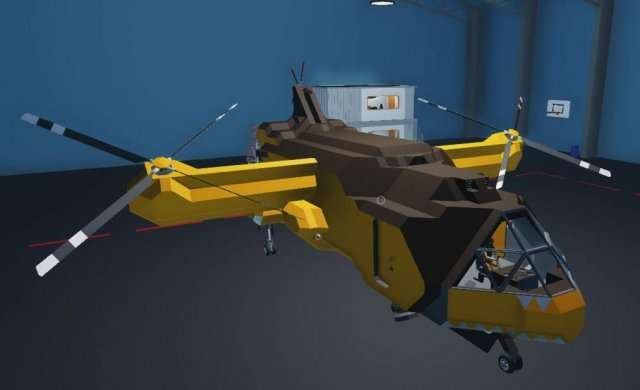
Designing an All-Around Helicopter for Medical & Rescue
Well, it’s finally here (this statement will age well after i’ve put in all the other sections, won’t it?) the helicopter.
No, really. I’m not kidding, apparently using the red cross without proper authorization is a violation of the Geneva convention, which makes it a war crime! You learn new and interesting things every day.
No, i didn’t opt to remove it, because i’m an Egyptian sun god. (Unless i’ve changed my Steam name at the point that you read this, then just imagine whatever is appropriate)
Jests aside, this is, without any jokes, the hull of the first helicopter (well, second revision of it) that i ever made in the game. I’ve stripped off pretty much everything out of it, so you only have the hull to work with. I’ve even removed all the connections, because i’m a terrible person! Some just want to watch the world learn…
But… what’s a helicopter?
You know those things called airplanes? They’re called “Fixed wing aircraft”, do you know why? It’s because their wings don’t flap, move, turn, or anything like that. They depend on something pushing them so that the air moves over the wings which are designed to generate lift which makes it so that when the plane moves fast enough, it’s pulled off the ground. Amazing, huh?
Helicopters are rotary wing aircraft. They’re called that because some complete genius decided that instead of having wings like planes… what if… you put those 2 wings on top of the plane, and instead of something like a prop engine pushing the plane, what if we just spun the wings around? I’m sure that ended in some sort of a massive explosion and fireball, but somehow we ended up with the helicopter as a result.
“But i didn’t ask that, you’re just putting words in my mouth!”
Oh by the way there’s going to be an unusually large amount of theory in this section, because understanding how helicopters, and their props work is the key to making a good one. Thankfully the previous section takes care of a lot, so let’s actually do something concrete.
Let’s build stuff before you get bored of the wall of text
Make this extremely crude addition to the helicopter, the components in question are a throttle lever and a tail rotor
“But that’s not a propeller, and that’s not where a tail rotor goes!”
Shush, don’t make fun of the tail rotor’s size or where it’s situated. It’s a perfectly capable helicopter rotor in its own right. Plus it’s easier to fit on there. Link up the tail rotor’s Yaw to the throttle lever, and wire up some electricity for the throttle lever. Change the throttle lever’s properties so the range is -1 to 1.
Now just go ahead and play with the throttle for a while. You see what the rotor’s blades are doing? This is something that’s called the collective. Also super secret amazing hidden feature: click E or Q on the tail rotor to fold it. Magic.
Nobody expects the Spanish theory section… especially when it’s written in English
“But i thought that was the theory section…”
Yes, sorry, it wasn’t, but i promise this part is actually shorter than you think.
Collective is nothing but the attack angle or prop pitch, but for helicopter rotors. It’s actually simpler than apparent: The higher the collective, the more lift the prop provides. This also means that it has more drag, so the engine has to give out more torque to rotate it.
The reason i’ve asked you to also hook in negative, is because negative collective (in case of tail rotor, helpfully labelled yaw) is also a thing. This allows you to turn left and right with the tail rotor, or make an upside down propeller provide upward lift.
If you’re unfamiliar with the “six degrees of motion” terminology, here’s the simple explanation:
- Yaw: Turn Left or right
- Pitch: Tilt up and down
- Roll: Tilt left or right
“Can we stop with the theory now?”
No, because i’m ending this section. Ha-ha, the building part you were looking forward to was in the next section all along! Now you know how Mario feels when he finds Toad instead of Princess!
Also delete that tailrotor and throttle from the side of the helicopter, we won’t be needing them.
Designing an All-Around Helicopter for Medical & Rescue pt 2…ish, But Not Really
First things first, let’s examine the helicopter. The particular importance, like with the speedboat is the center of mass.
“Wait, is this another theory section? I thought you said…”
Super quick, super important, ok? No funny stuff, i’ll just get it out of the way, deal?
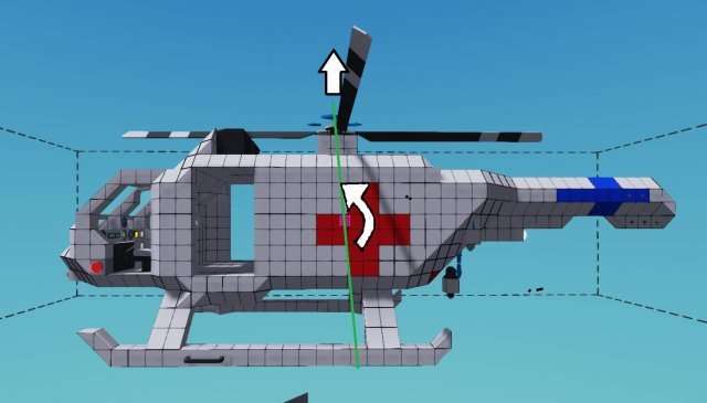
As this highly professional MS paint shows, because this is a pulling, instead of a pushing type of motor (unlike the speedboat for instance) the force on the imagined “lever” is a more rotational type force that forces the nose to pitch down. Imagine like you were dragging it around on a string. This is what the force is like.
Misaligned center of mass also causes a significant amount of instability, so it should be of utmost importance to try and align these as much as possible for any helicopter. The batteries are situated where they are to try and adjust this balance.
It should also be of note that when fuel drains, it can easily shift this center of balance, so fuel tanks should be situated in line with center of balance.
Now let’s actually get to building
Since this is a general purpose helicopter, and comes with a winch, a single diesel engine lacks power to carry stuff, but would be OK for ambulance only. If you only care about range, want to make it lighter and a medical rescue helo, you can follow this guide by building a central single engine instead.
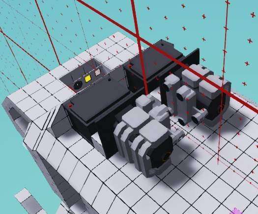
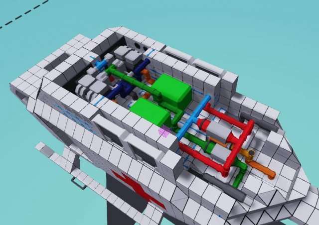
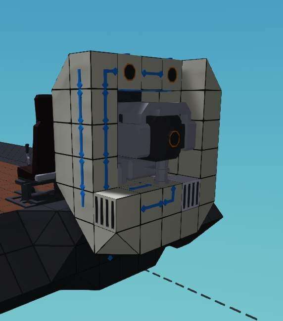
My personal preference is to make the twin engines in designs like this “kiss” eachother. One tile gap between them allows extremely compact engine designs without compromising utility. As before, this isn’t really a pipe beauty guide or anything like that, so i’ll walk you through the less obvious ones:
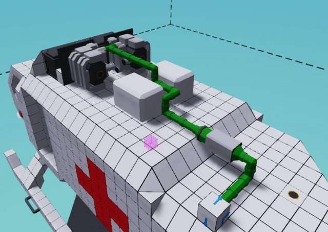
The fuel pipe has a fluid intake situated on the back-end of the craft. A rear-mounted single pump is useful to have for pushing the fuel all the way to the tanks. It might not be a necessity, but it really isn’t a problem on electricity drain either way.
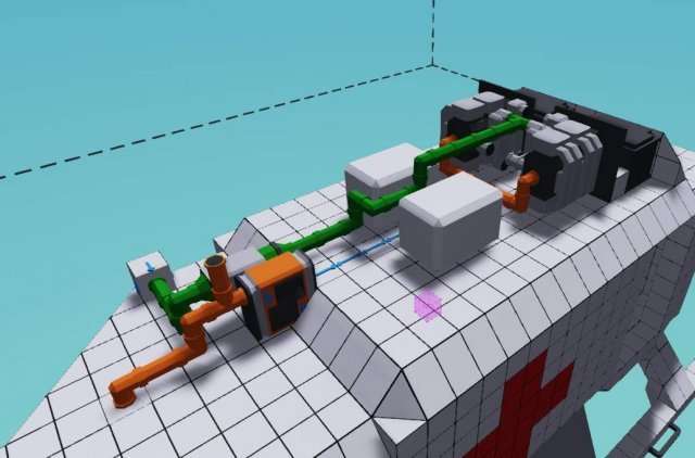
Hook up the drivetrain to the already existing tail and introduce a gearbox along the way, where and how is up to you. The tail exists already for your convenience, and has a sneaky little generator behind a clutch so we can keep electricity topped up.
How you design the rest of the engine bay, including cooling and air intakes is up to you. This will not use a lot of cooling, the double radiators i used are mostly for aesthetics (and possible future tuning). What’s important is that you have all that you need hooked up.
Now would be a good time to hook up that engine by locking its throttle to 1 with a constant number and giving it a go. It’s easy at this point to see the engines still so you can tell what issues (if any) they have. Though you could also just remove a part of the interior ceiling to see them, i guess.
My engines stabilize at around 93 and 91 degrees. There’s often some weird variance between 2 sides, up to even 10 degrees. Don’t let it bother you.
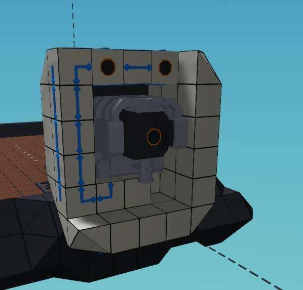
The crown on top of the helicopter
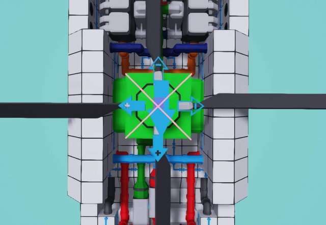
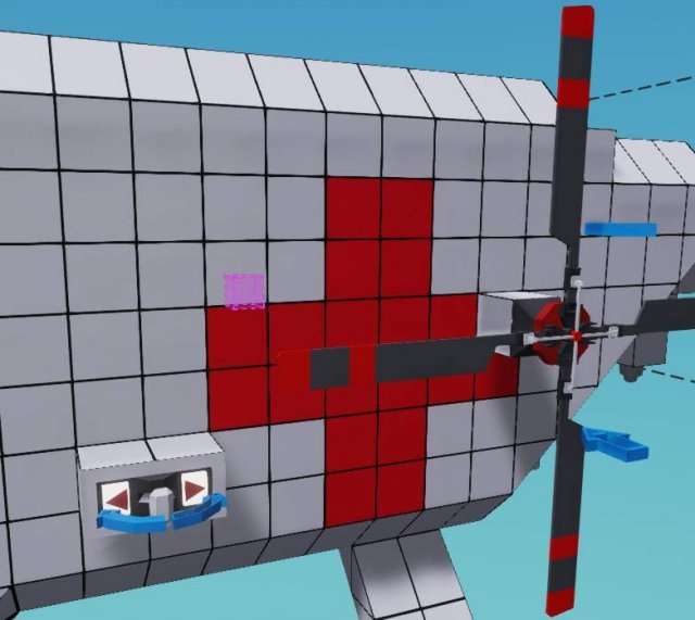
Finally, it’s time to put the cream of the crop on the top. Make very sure the large rotor is as close to in line with with the center of mass as possible.
In the picture of mine you can see i drew a pink X on top of the rotor housing. You should notice 2 particular things:
- The large arrow is nowhere near centered and is a poor indicator for it being near the center.
- My arrow is pointing backwards.
The latter just means i will have to inverse my inputs with a multiplication of -1. This is the only time in the guide i will refer to this, as it’s very possible with your engine design you can simply place your rotor the right way round.
Hook up the rotor to the drivetrain behind the gearbox, then do the last bit of covering up of the engine and beauty work, because the engine is going away now. We won’t be seeing it again unless we need to work on it again in the future. Finally, sneak a tail rotor in place, there’s a pipe eagerly waiting there. You can install rudders if you’d like to have them.
This is a good time to test those engines again.
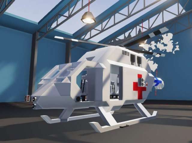
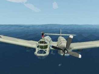
Sure, it looks like a dopey humpback, but it’s done from a mechanical standpoint… but why doesn’t it fly even with the prop at positive (locks collective to 1)?
A sneaky anecdote
So, there’s 2 different types of helicopter:
- Old style: The prop is completely locked on positive, and engine throttle determines how much lift is gained.
- Modern: The collective is variable and determines the lift, and electronics control the throttle to keep it at a desired RPS.
There’s up and downs to both of these systems, the old style is more reliable, as there’s less moving parts, but the modern is significantly more flexible and responsive to input as it doesn’t rely on throttling a combustion engine.
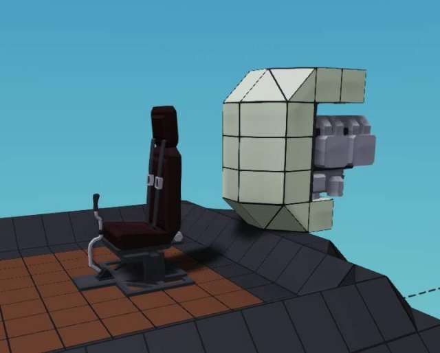
Wiring it up
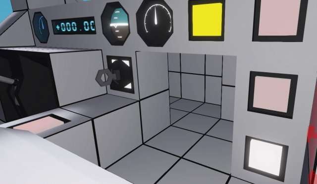
You will find a lot of the cockpit pre-wired (and mysterious nonfunctional controls for other stuff that aren’t there, hmm), the main part we’re interested in is the gyro already installed at the back of the seating compartment.
As doing an electronically controlled engine requires significant electronics, i will leave that for extra credit, along with a few other things. We will be making an old style one.
First, install a throttle lever to control the engine throttle, then wire up these inputs on the gyro: Roll, yaw and pitch, leave the up/down alone. Oh, and something to start the engine would be nice. Finally slap the gear ratio of the gearbox to 1:2.
After doing all that, wire the stabilized output of the gyro to the relevant outputs. The yaw goes to tailrotor, pitch and roll go to the rotor above. You know that part which i said i won’t bring up? I lied. This is just a friendly reminder that if your rotor is backwards, your stabilized(!) pitch and roll are reversed. Likely your stabilized yaw is also reversed with how the tail rotor is faced.
You may play with stuff like the ratio later on your own, the reason i’m not going into more detail and explaining the choices better here is because i’m running close to the size limit of this section of the guide. I will save more of the detailed explanation for the extra credit part.
Test run? Test run!
Quick troubleshoot:
- Does it just roll like a washing machine tumbler?
- Invert the stabilized roll going to the rotor
- Does the engine blow up?
- Limit the RPS lower than 20
- Does it stutter weirdly at high throttle?
- This is engine tremble, because the engines are peaking out with their RPS and responding to the changing load while they’re spooling up their own rotations. It’s an unavoidable part of using this old style hookup. You can get rid of most of the engine tremble corrected by the gyro by dividing the stabilized roll input by a relatively large number, like 5, but this is fixing the problem and not the cause.
Those are the only problems that are really possible for this setup…
Finally, test at what point it lifts off. For me it’s 0.55. It might be wise to set the minimum throttle slightly below this for a good landing setting, something like 0.53 worked for me. It is an absolute power house, but with the rather difficult throttle control it’s really not easy to handle, but it most definitely flies, and it flies hard.
In other words, a perfectly functional helicopter, good job!

Extra Credit: Engoodening the All-Purpose Helo
If Internet Historian says “Engoodening” is a word, it sure is a word!
The entire section is practically dedicated to making an electronic engine control module, and it’ll be quite light in theory, but if you can’t think with logic gates, it’ll be quite complex. Let’s get the theory out of the way:
The theory section
We want the small engines to hover around a desired RPS, and we need the throttle to be automatically controlled to do this. There’s 2 ways of doing this:
A physical throttle lever that is controlled by the electronics
- This gives us an easy to see visual representation of what the script is doing.
- In emergency situations we can have an override that disables the script from controlling the throttle.
- It’s easy to disable the automatic throttle control and turn the throttle to 0 to shut off the engine.
An internal throttle control that’s handled inside the microcontroller itself
- This is significantly more responsive than the actual throttle lever even with high throttle sensitivity.
- Requires less size as a microcontroller as it doesn’t need the 2 outputs to the throttle lever.
- Requires less space in the cockpit.
Usually i would favor the bottom one, but it does require more work to tune the sensitivity of the counter, and is generally a bit more difficult to design. We’ll go with the simpler, if still more striking option.
First things first
If you’ve followed the guide so far and are not here to look up upgrades for your helicopter, we only have a throttle control, without the up/down of the gyro being engaged. The up/down control from the gyro will control the collective of the helicopter blades to provide lift. At 0 engagement it will make the helicopter “neutrally buoyant”, or close enough. In reality this won’t be quite exact, as every helicopter and situation is a little bit different.
Here’s what we’ll do:
You can either hook up another throttle lever for the up/down adjustment in the cockpit, or simply wire it to up/down on the seat. For the throttle lever you’ll need -0.4 as the minimum for a good landing setting.
After hooking up the lever to the gyro, hook up the stabilized up/down to the collective of the helicopter blades, then make very sure to set the prop of the heli to neutral. This will allow adjusting the collective of the prop itself.
Return your throttle’s minimum setting to 0, then connect its electrics to an electric relay so that it can only get juice when the relay is on. If you haven’t used one before, it’s an electric switchbox that’s controlled by an on/off signal. We will use this to disable the manual use of the throttle lever when the override is on.
The relay isn’t absolutely necessary, and you can have a 2×2 microcontroller instead without it, but adding it won’t be much trouble.
Let’s get to the electronics, with some pictures!
Let’s dig a nice hole for that microcontroller, the 2×3 space hidden behind the panel should be enough. You need to dig in there a little bit, but it’s fine.
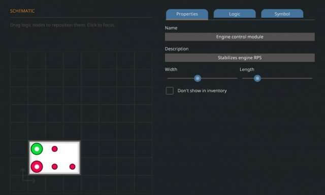
Let’s design the microcontroller now, we’ll need the following:
- Override input (on/off).
- RPS Input (number) > one is enough, the engines are stuck on the same drivetrain.
- Throttle up output (on/off).
- Throttle down output (on/off).
- Relay output (on/off).
We’re going to use a similar layout to this. Let’s lay out our already existing pieces in a sensible manner.
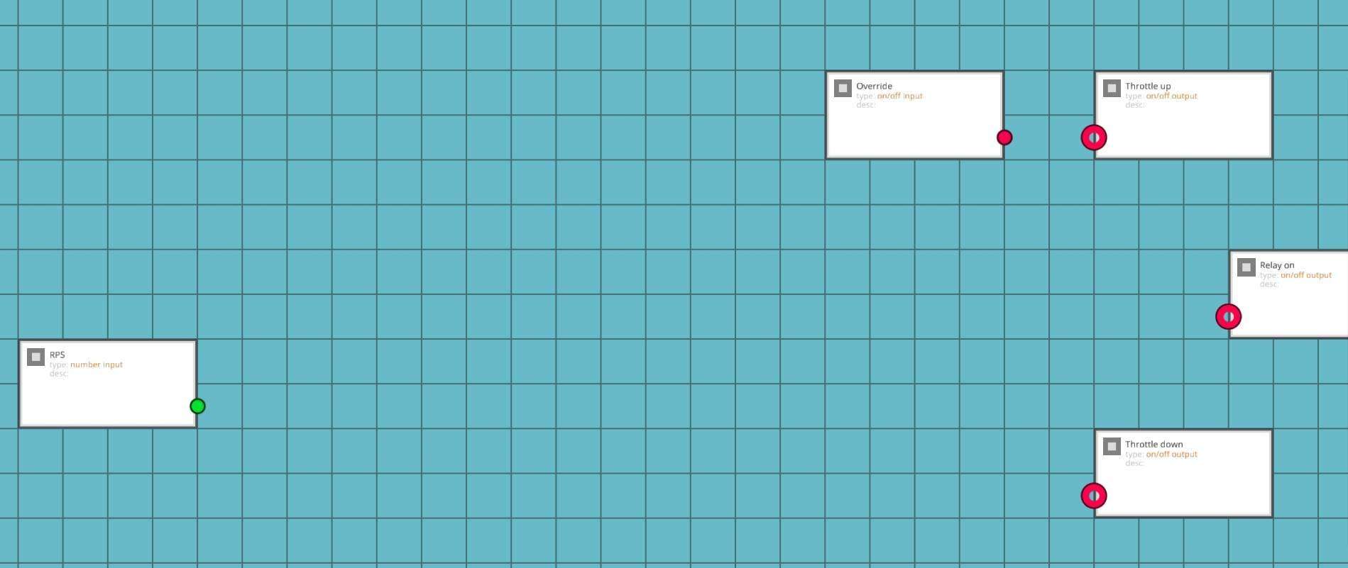
Nice. The far left will feature RPS only, because we’ll need some logic to handle it, the right hand side will feature our assortments of other stuff. We will be using the override later, so it’s off to the side.
Chips we need:
- Less than > Hopefully obvious.
- Greater than > As above.
- Property number > Easily modifiable number that you can adjust in properties.
- Add >
- Substract > These 2 modify the property number.
- 2x Constant number > Set at 0.5 so we have a desired range.
Lay them out as such
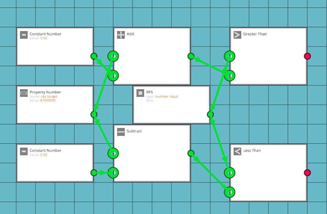
I will try to explain the logic behind these in the first paragraph after every picture, if you’re already decent with logic, you can skip this part. Firstly, we’re using 2 constant numbers only so it’s easier to read. The incoming number sets the desired target, the addition and substraction creates a range of +0.5 and -0.5 from that value, this compares the RPS coming from the engine to see whether or not it is larger or smaller than the desired value.
We can also make it so that the desired value can be determined by things like keypad input, but that’s for you to do if you wish to do that. Now that we have the comparative logic in place, let’s handle the outputs logically
Chips we need:
- Or > So that either greater or lesser than input enables the relay so that the script can modify the throttle.
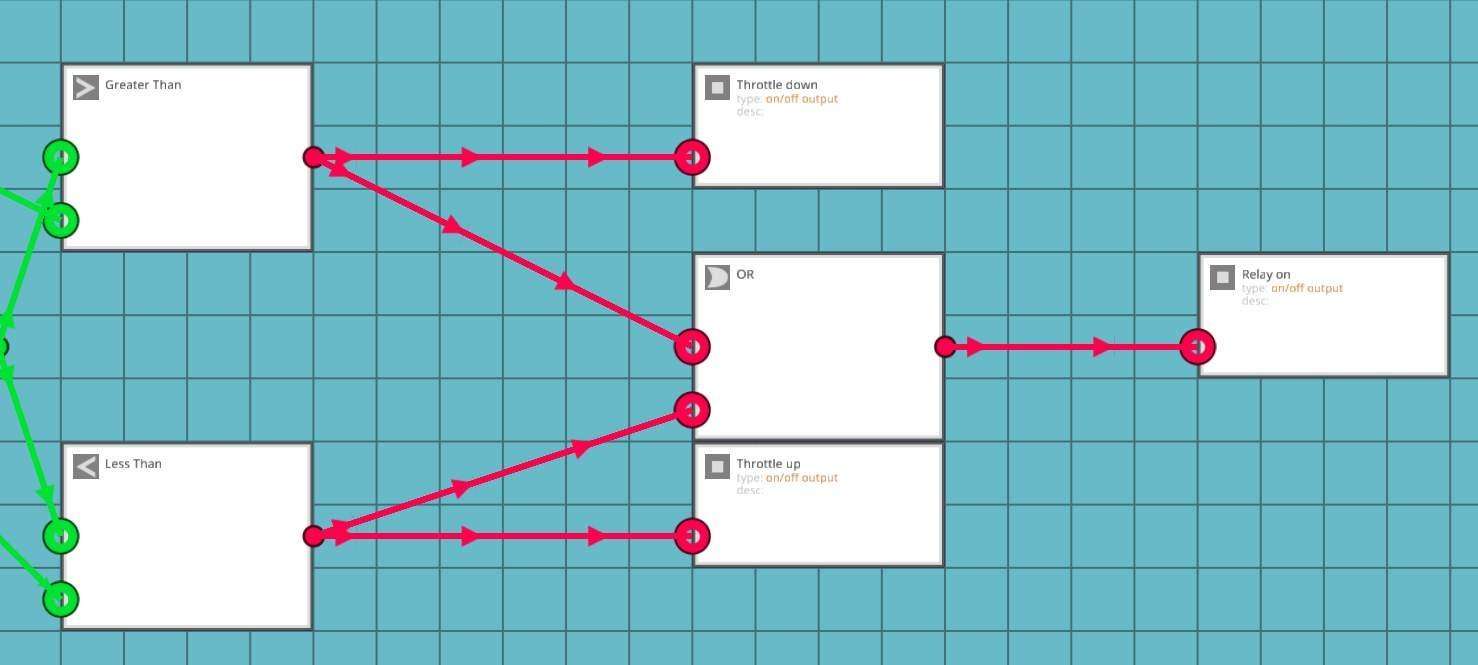
Well, that was simpler than expected, wasn’t it? This setup enables the relay whenever either greater than or lesser than condition is met, and allows the adjustment of the throttle. However, it disables the relay when either condition isn’t met (the throttle is in desired range), and thus disables you handling the throttle lever.
Ok, it’ll take a little bit of thinking to do the override properly. Our easiest way is probably to attack the numerical section of the electronics, as explaining how to override the binary logic itself would be a little bit more complicated.
Chips we need:
- 2x Numerical switchbox > We switch out the RPS input for a desired value.
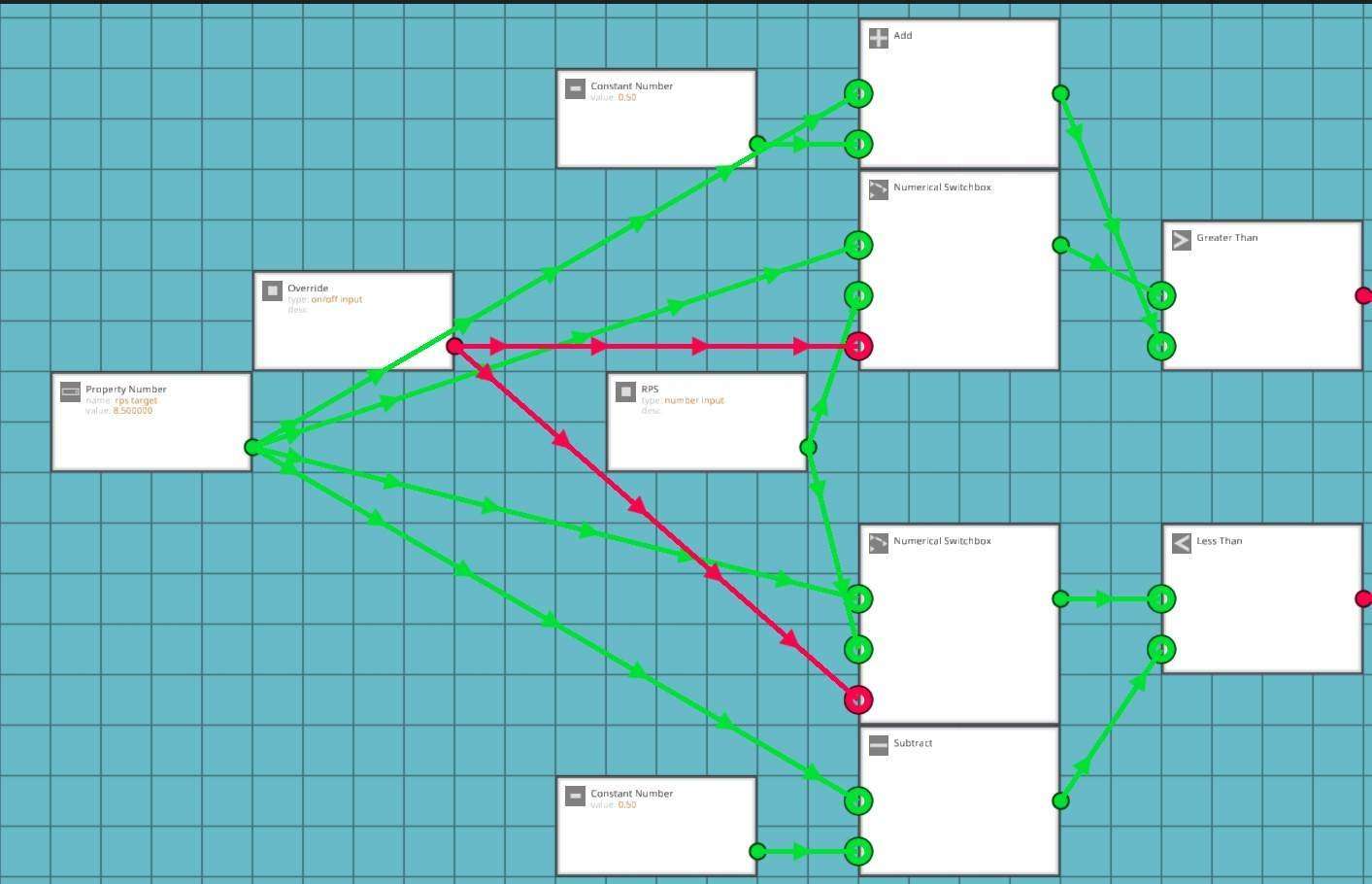
It might be a little hard to read, but the RPS values are on the “off” state inputs of the switchbox (when override is not on), and the desired number is on the “on” state of the switchbox inputs, which are linked to the lesser and greater than A ports. This means that when override is on, the electronics think that the engine RPS value is always at a desired state.
We’re still missing one little thing, forcing the override to enable the relay
Chips we need:
- 2x Not gates > Optional, i use these in pairs (they cancel eachother out) to route the signal. Makes it easier to read.
- Or > For yet another fork to the relay input.
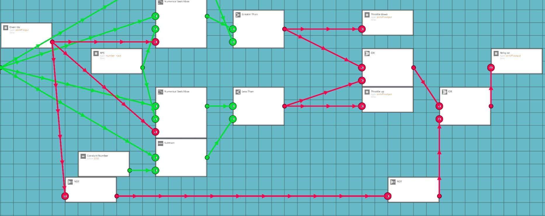
This makes another OR-fork for enabling the relay. As you can see, the paired NOT gates makes a nice routing for the signal, instead of it just crossing over everything.
I’m sure you can figure out where and how to wire these, but just in case there’s someone who’s still very much learning english, or simply having a confused day (and doesn’t want to ask the silly question) here’s the breakdown:
- RPS takes in the RPS value of any engine.
- Override takes in a toggle button.
- Throttle up goes in to the up input of the throttle lever.
- Throttle down goes into the down input of the throttle lever.
- Relay connects to the electric relay that is connected to the throttle lever.
If you’re flying the helo made with the section above, set the desired value to 11, then set the gearbox to 1:3.
Testing time
So… it kinda works. If you gun the collective, but you soon have to hit the override and handle it yourself. What’s wrong?
What’s happening is that the script is failing to take into account that the engine is taking time to respond to the throttle input. It’s trying to adjust the throttle wanting an immediate reaction from the engine. This would work with an electric motor, but we need to look at something else.
Let’s go back to the script for one more final swing at it.
Note: This section ran out of text space, how awkward.
Extra Credit: Engoodening the All-Purpose Helo (Cont.)
One more tweak, that’ll surely do it!
Chips we need:
- Delta > High school maths. The difference of a value given a unit of time (in this case, 1/60 of a second).
- Greater than >
- Less than > These 2 for comparisons.
- 2x Constant value > To be compared against.
- 2X and > The RPS value is below and not rising or The RPS value is above and not dropping.
- 2X not > Read above.
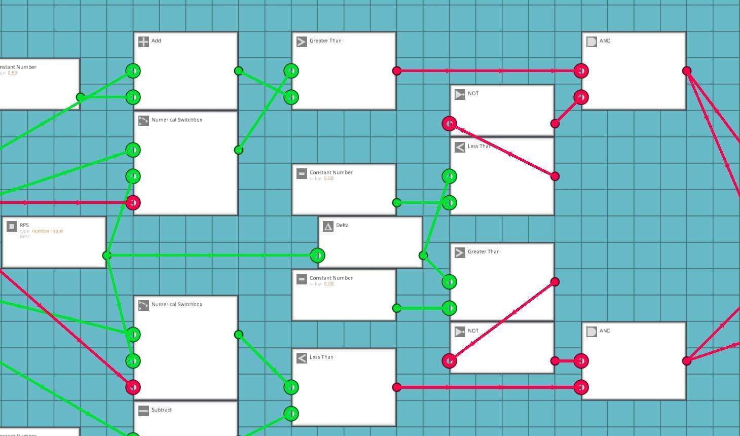
It’s easier to describe the logic here as the computer reads it. Remember, delta looks at the difference of the RPS value, so we will know if the engine is spooling down or up.
Here’s essentially what the entire chip does:
- If RPS is less than desired value and not already rising: Enable relay, increase throttle.
- If RPS is more than desired value and not already dropping: Enable relay, reduce throttle.
- If override is on, RPS = Desired value: Enable relay.
The 0 setting for the constant numbers is not error-free. Something like 0.01 or 0.005 would likely work better. You’d have to observe the delta number to figure out what’s a good value for it. Calibrating this value is pretty engine setup specific, but it won’t take too much trial and error to figure out. All it takes is making a temporary number output and getting the readout on the delta value on something so you can watch the decimals work.
Let’s test again, like we did last summer
Hey! If you wired up everything correctly, it’s perfectly functional now. It responds relatively fast, and stabilizes the engine by throwing the throttle around.
The only problem with this is that it does so little bit too eagerly, this is mostly a very mild annoyance type of problem, as it revs the engine up and down to keep within the target. The only way to deal with this particular problem is to make another logic section that handles the fine adjustments of the throttle lever itself. Basically this is what you need to have:
- If RPS is within +/0.3 of desired value: Do very short touches on throttle to find the sweetspot.
- Something more reactive likely works best, like:
- If RPS is less than 0.3 more than desired value and delta is above 0, reduce throttle for X amount of ticks
- If RPS is more than -0.3 less than desired value and delta is below 0, increase throttle for X amount of ticks.
I’m not going to explain how to do this in detail, but it’s not too hard to figure out. Here’s a hint: The timer logic blocks can be set up to output signals for a specific number of game ticks. You can multiply the absolute delta value to fine-tune the throttle, but you’ll need to experiment to get it right. You’ll likely want to use the timer that sends a signal when its duration has not yet been reached.
If you want to make adjustments every single tick and are having trouble with the clock signals, you can use a combination of a toggle button set to “push” and a blinker. This will give you 5 or 10 signals per second, instead of the usual 60. Alternatively, you could just use a PID controller, but that’s less engaging.
Success!
Extra Badly Designing a Combustion Engine for Boats
This section is mostly meant for what it looks when you design a section of a guide without testing the concept firsthand. I left it in as a curiousity more than anything else, please do not follow this for your sanity’s sake.
Let’s start building. My outboard will be slightly creamy with red racing stripes.
The engine should be seated so that the coolant in/out piping is either in line, or one behind the last block on the Dinghy. Yes, it will be comically huge because we’re using the “small” diesel engine, but this is fine.

This is an easy way of dealing with cooling. If you want a rotary version of the outboard, you’d have to integrate the cooling into the downward reaching part of the outboard with the prop, but it’s relatively easy to pipe.
When dealing with exhaust and fuel, we should bulge out the outboard’s cowling (the shell of it) so we can hide encased piping where we want it. This was my design of choice, but you can just pipe it out the side as well.
This is my solution for the air intake. Unsurprisingly, the most important feature of the air intake is to take in air, but at the time of writing the engines don’t care if water gets in it even for a good while, you don’t need to make a filtration system.
For the tank i would use a custom enclosed tank, but since this is attached to a dinghy and the weight would be absurd, i’m in fact going back on that design and just tucking on a small tank, as it’s enough for testing, and for later use the outboard can be taken off and used as a subassembly!
Finally, we should hide a gearbox in the bulky form of the comically huge outboard engine.
Make sure that the gearbox’s arrows are pointing toward the engine, since we want to increase the RPM.

Then finish the rest of the cowling and make sure the damn thing floats.
Testing time!
Now as said before, we’re working technically against a constant load. So wire that sucker up in any way you like, try for 2 gear ratios that sound feasible to you (like 2:3 and 1:2) and prepare to test it out.
Here’s the dials (or other readouts) that we want:
- Engine heat (optional, but good to see).
- Engine RPS (absolute must for fuel economy tuning).
- A visible way to see whether or not the gearbox is toggled on.
- Fuel tank’s contents.
- Speed.
What we’re looking for
Signs of the gearing being too low:
- RPS increasing above 8 on a small engine (unless you don’t care about fuel efficiency, then 10-12 RPS is a good target).
- The boat becoming unstable (this can be addressed with hull design).
- Excessive fuel consumption.
Signs of the gearing being too high:
- Excessively slow start (slow start is ok, since we have 2 gears to play with we can use the other one too).
- RPS stays constantly below 6 even after reaching full speed.
- It doesn’t start at all (very hard to do in a boat).
After flipping my boat a few times with the excessively heavy outboard, i’ve come to a value of 5:9 for the gearbox being perfect. RPS sits around 7.2 and rises up to 9 if i catch some air, but never enough to flip the boat if i feather the throttle a little bit. It can reach about 10m/s before becoming unstable.
So what have we learned (possibly):
- Heavy outboards on small rubber dinghies are dumb and cause it to flip.
- If there was more weight toward the front of the craft, we could go faster without flipping.
- Getting that right gear ratio for a boat requires a few test runs, so it probably should be done last.


Be the first to comment