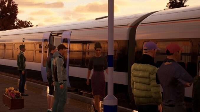
Metrolink Rotem Control Trailer
Overview
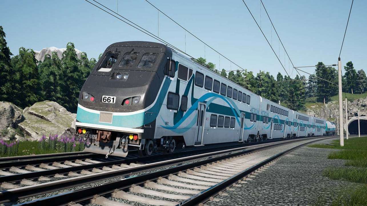
Dating back to before the F125’s time, the Rotem equipment for Metrolink arrived in 2010 as the start of a wider fleet replacement scheme for the former Bombardier bi-level coaches. Delivered in both standard trailer and control car configurations, the Rotems would continue to offer the same level of push-pull flexibility as is standard on many US passenger lines. As part of Metrolink’s naming scheme, the Rotem equipment is known as the “Guardian Fleet”.
With older stock still in place, regardless of what coaches are used, Rotem cab cars are now always found at the non-powered ends of trains, with former bi-level stock’s cabs plated up and out of use. This makes the striking appearance of the Rotem nose a common sight, and on the Antelope Valley Line, it leads the way southbound into Los Angeles.
- Manufacturer: Hyundai Rotem
- Build Location: Pennsylvania, USA
- Build Date: 2010-2013
- Number Built (BTC): 80 trailer cars
- Number built (CTC): 56 control cars
- Capacity (BTC): 179 seats (185 total)
- Capacity (CTC): 173 seats (179 total)
Metrolink Rotem Control Trailer Cab – 1/2
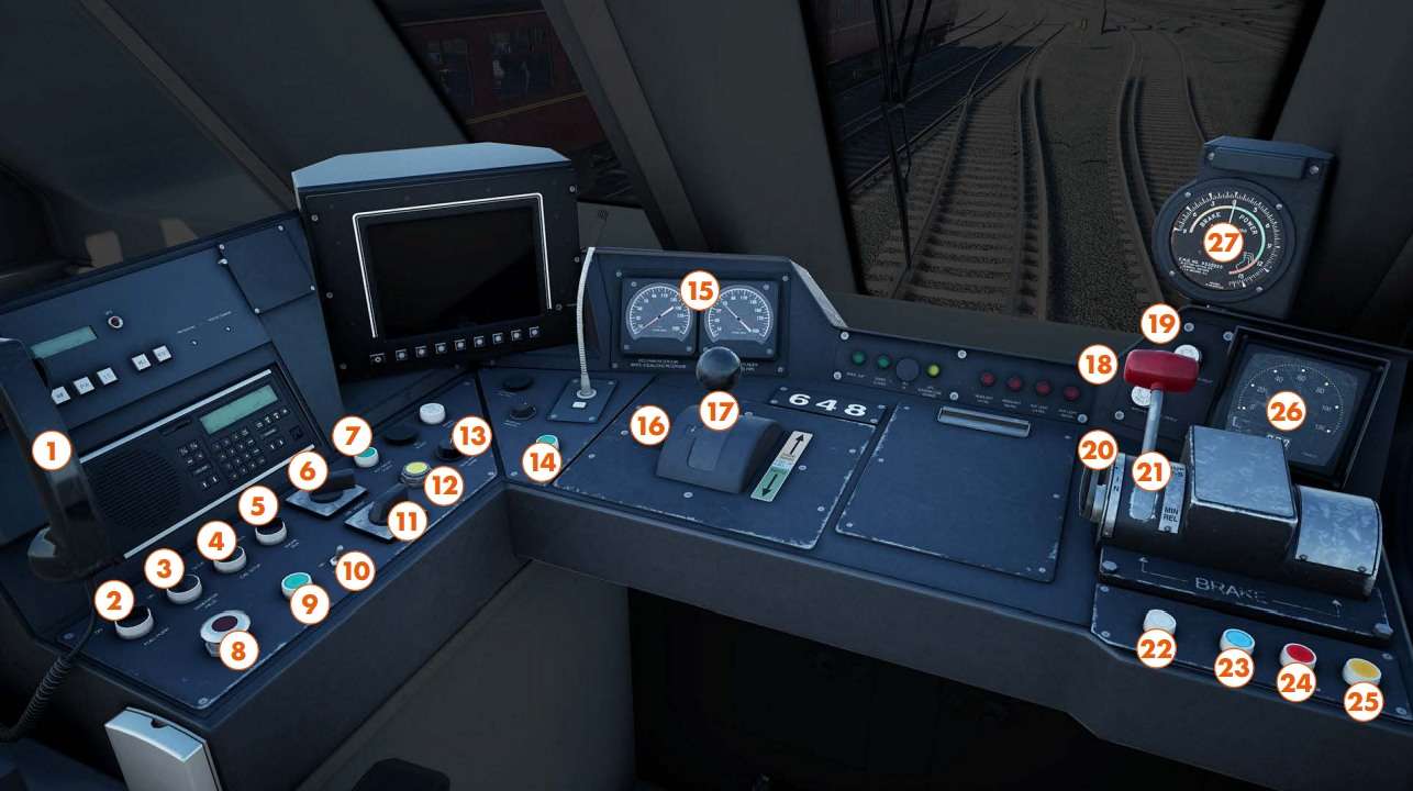
- 1 – Contact Signaller Phone
- 2 – Fuel Pump Switch
- 3 – Generator Field Switch
- 4 – Cab Setup Switch
- 5 – Engine Run Switch
- 6 – Cab Heater Switch
- 7 – Auxiliary Light Manual Flash Button
- 8 – MU Stop Button
- 9 – Attendant Call Button
- 10 – Cab Light Switch
- 11 – Head and Aux Lights Switch
- 12 – TMS Reset Button
- 13 – Gauge Light Dimmer
- 14 – Horn Sequencer Button
- 15 – Brake Gauges
- 16 – Reverser Handle
- 17 – Master Controller Handle
- 18 – Wiper Middle Switch
- 19 – Wiper Right Switch
- 20 – Automatic Brake Cut-Out Lever
- 21 – Automatic Brake Handle
- 22 – Sander Button
- 23 – Bell Button
- 24 – ATS Acknowledge Button
- 25 – Horn Button
- 26 – Speedometer
- 27 – Tractive Effort Gauge
Metrolink Rotem Control Trailer Cab – 2/2
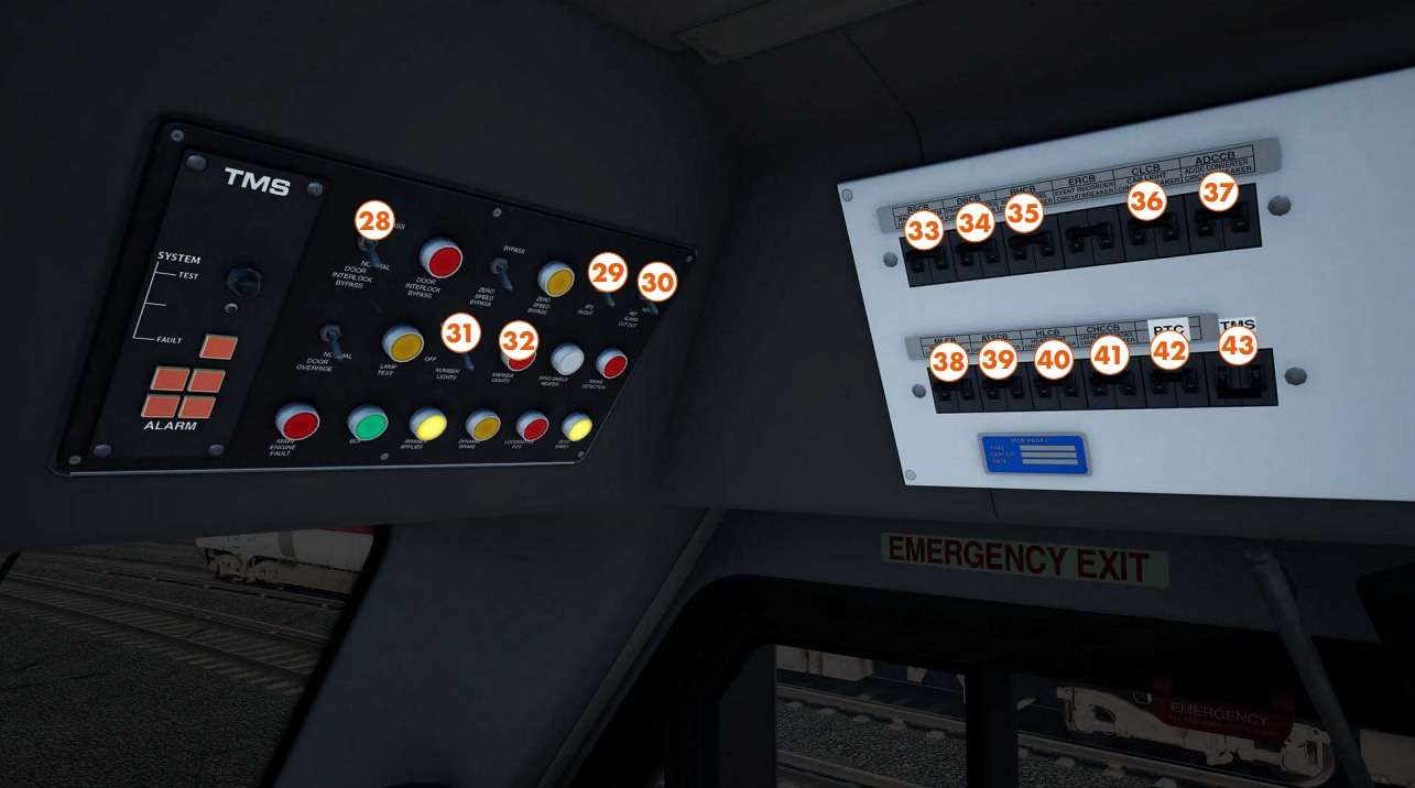
- 28 – Door Interlock Bypass Switch
- 29 – ATS Cut-Out Switch
- 30 – HEP Alarm Cut-Out Switch
- 31 – Number Lights Switch
- 32 – Marker Lights Button
- 33 – Radio System Breaker
- 34 – Dynamic Brake Control Breaker
- 35 – Bell and Horn Control Breaker
- 36 – Cab Light Breaker
- 37 – AC/DC Converter Breaker
- 38 – Marker Light Breaker
- 39 – ATS Breaker
- 40 – Headlight Breaker
- 41 – Cab Heater Control Breaker
- 42 – PTC Breaker
- 43 – TMS Breaker
Procedures & Unique Features
Cab Setup
- When you are getting ready to start a service from the Rotem end, it is important that the first thing you do is turn the Cab Setup Switch to Setup, this is the main switch which tells the train that the cab car is in control, if you touch any controls first without confirming the position of the switch, the setup procedure will not be valid, and you will have to start again.
- Another common switch to check in the setup procedure, much like in the F125 itself is the Generator Field Switch, this must be set to On.
Brake Controls
- When setting up, you will need to cut-in the automatic brakes to activate them, the control for this is quite different when compared to the F125 but the overall function is the same.
- From the control car, you can still take full advantage of the dynamic braking on offer, just remember that dynamic brakes are not designed to stop a train, so the blended mix of dynamics and air is needed.
Other Bits & Bobs
- Getting into the cab is not as straightforward as it seems, you must enter through any of the passenger doors and make your way to the cab end of the train, then walk up the stairs to the upper deck, and navigate your way along the side of the cabin where you will find the internal cab door.
- Much like when in the F125, the train formation features Rollback Prevention, so while best practice is to apply power before fully releasing the brakes, if you do start to run in the wrong direction when setting off, you will be kept within safe limits.


Be the first to comment