
This is an in-depth guide how to build your own electric PIN Code security system.
Building Electric Security System
Introduction
This guide shows you how to make a 4-digit PIN code security system. You can build it yourself using electrical parts. I’ll explain how each part works and how they connect. It helps if you know a bit about wiring, inverters, and auto switches before you start.
Some of the security features this system handles are:
- Any number of input buttons supported (more can be added or removed).
- Any number of digits in the PIN Code supported by adding more modules/locks (see below).
- When wrong button is pressed at any time, the entire system resets.
- Changing the PIN Code is as easy as rewiring a cable.
Of course this can be used in other scenarios as well as long as there is some way a user can interact with the system (buttons, proximity sensor, pressure plate etc.). A puzzle room where you have to stand in the right position and pressing the right button or something?
Words and Legend Used in This Guide
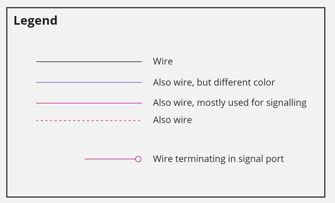
Each line in the diagrams are normal power cables. They may have different colors and shapes to emphasize different purposes or to distinguish them when they are overlapping each other.
Each blue Power node is always the same source of power. Sometimes multiple Power nodes are used only to make it easier to read the diagrams.
- Auto is the in game Auto switch.
- Invert is the in game Power inverter.
- Orange boxes in the diagrams are logical functions or other part of the system. Not items that you find in game.
Resource Requirements
This is the items needed to build the system:
- Auto switches (24x).
- Power inverters (13x).
- Buttons (4x).
- Power source.
System Overview
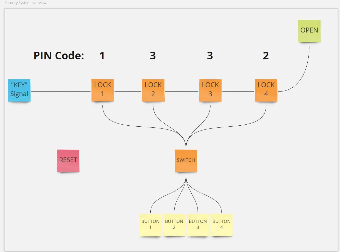
The basic idea behind the system is to have a signal that act as a “Key” and moves through the different locks. Once all locks are open the “Key” reaches the very end and can then be used as a signal, for example to open a door.
Locks and Buttons are wired via a Switch that makes it possible to use the same buttons for the different locks. The entire system work together so the Switch know which lock is expecting input, which buttons are right and wrong and how to reset the system should an invalid PIN be entered.
Locks and Security Modules

Locks and their corresponding Input Handling mechanism together make up what I call the Security Module which is responsible for two things:
- Open the lock when an Input Signal is received so the Key Signal can pass through.
- Once unlocked, redirect all incoming Input Signals to the next lock.
Looking closer at the Lock there is two Auto switches. The first one (top most) will let the Key Signal through once it’s opened with an Input Signal. It’s also looped to its own signal port which will keep the lock open even after the Input Signal is lost (for example when the button is released). Only when the Key Signal is lost (see Reset later) the lock will close again. The second Auto is there to prevent an Input Signal from opening the lock before all previous locks have opened. Technically this can’t happen with the way rest of the system is designed (as you’ll see later) and should be safe to remove.
I decided to keep it in anyway simply because I already had all the wiring done when I realized it and I kind of like the idea of having a module that I can later reuse for different purposes without redesigning it every time.
Worth noting here is that the locks are incredibly simple in that all they do is open up once an input signal is received. At this point we have no idea how that signal was generated or which button was pressed. We received the signal, we open.
The Input Handling mechanism has Auto and Invert switches that work in pair. By default (no power on the red / pink signal cable) the Invert will let the Input Signal through to the lock. When the lock is opened and powering the signal cable, the Input Signal will instead go through the Auto switch and on to the next module.
Having the Input Signal being passed through all Security Modules like this make it really easy to chain multiple modules one after the other without having to rewire everything. It’s just a matter of connecting the outgoing signals from the previous module on to the next. This also mean that we have a built in way of redirecting any button press to the correct module.
For example let’s say the PIN code is 1111, each time Button 1 is pressed it will go to a new module thanks to the chaining.
This is how we advance further in the security system and when all locks are opened the Input Signal is just dropped (not connected to anything).
Dealing with Multiple Buttons
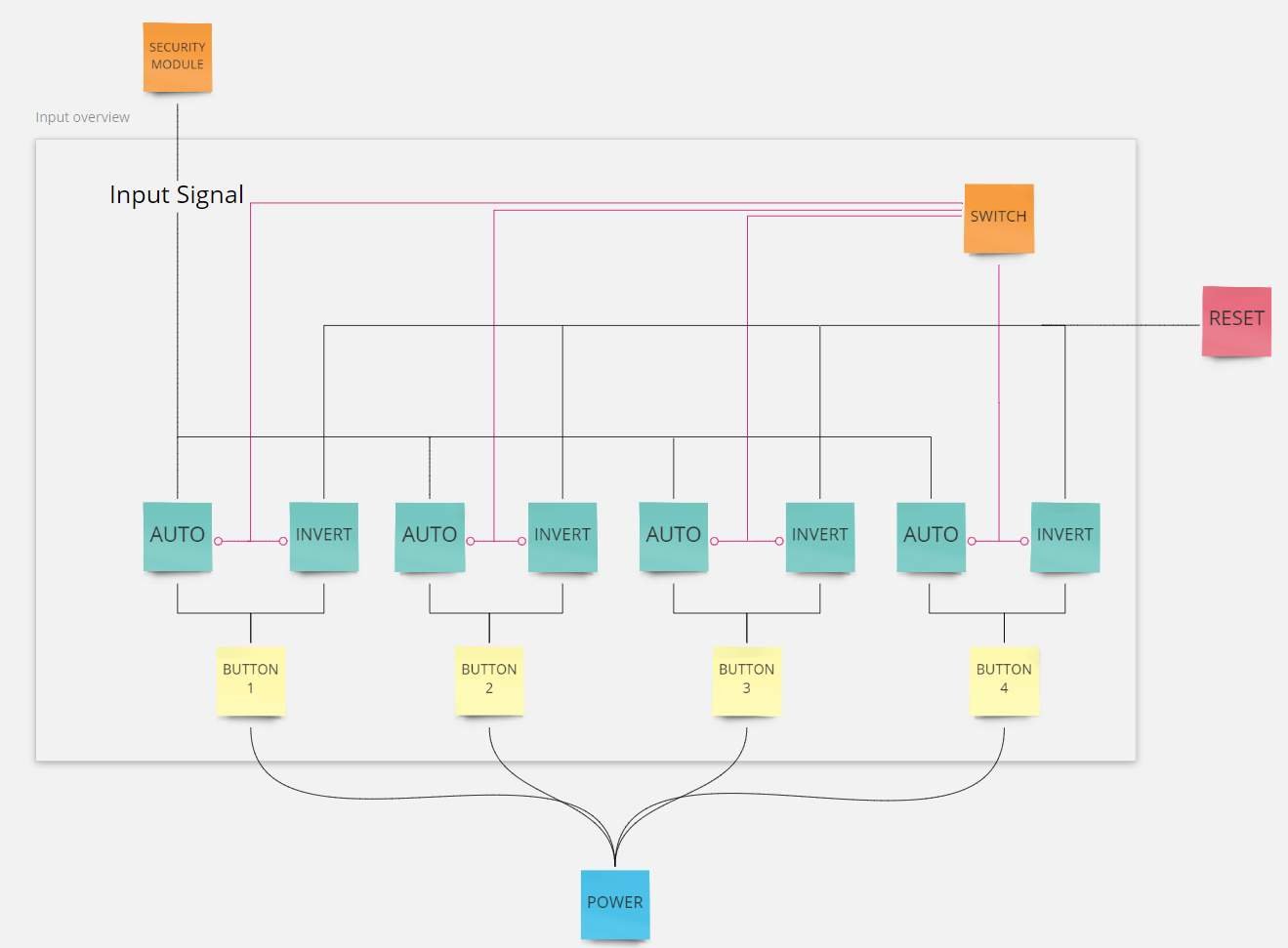
Any reasonably good security system will support multiple input buttons, so it only makes sense that we do to!
Since the Locks open as soon as an Input Signal is received, we need a way to control that only the correct button can be pressed at any given time depending on how far we’ve advanced in the system (how many locks we’ve opened). This is done in two parts:
- A mechanism for enabling / disabling the buttons.
- Logic to enable the correct button.
The mechanism for enabling / disabling a button is really simple and we saw it in the Security Module earlier, it’s an Auto / Invert pair with a shared signal cable (a.k.a. Signal Group). By default (no power on the signal group), pressing a button will send power through the Invert switch which will result in a Reset of the system. With power on the signalling group and pressing the button will instead send its power through the Auto switch and to the Lock.
This is a great start for dynamically controlling which of the buttons should trigger the locks. However, we need a way of deciding when to power each of the signalling groups and we do this with what I call the Switch.
Switch
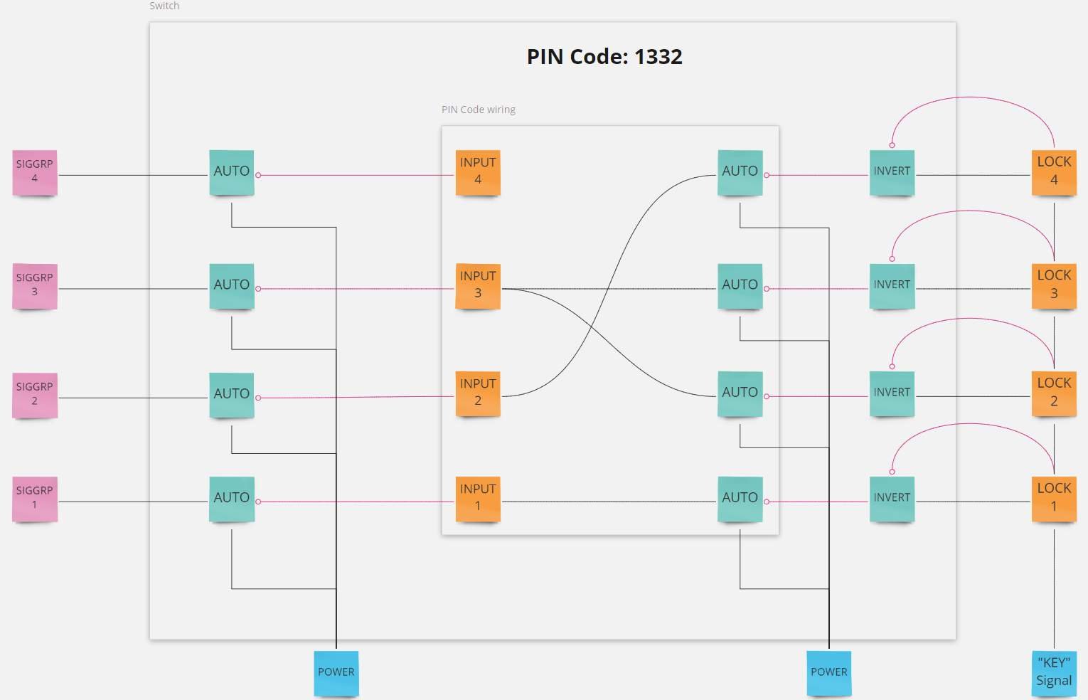
The Switch is where all the magic happens. This is what tie all the other modules together and give life to the concept of PIN codes by connecting buttons with locks in different stages.
We already have a way of enabling / disabling buttons so what we need to do is let the Switch decided when this should happen.
Perhaps the easiest way to look at the switch is by separating it into three parts. From right to left (don’t ask me why I decided to draw it this way…) is the input, followed by the PIN Code wiring and then the output which is what powers the signal groups and enable/disable our buttons.
You can think of the orange Input x boxes in the diagram as ports in a patch panel and doesn’t really correspond to anything in game, I just find it easier to read the diagram with them there when I do the wiring.
Starting with the input part, each lock is responsible for sending its own button signal (the signal that will tell which button that should be enabled). Each lock start by passing the incoming Key Signal over to the PIN Code wiring which will enable the correct button. Once the lock is opened it will send the same Key Signal to the Invert signal port, effectively blocking its own button signal so that it doesn’t keep the button enabled. The Auto switch inside the PIN Code wiring is to avoid feedback loops when connecting the same button to different locks.
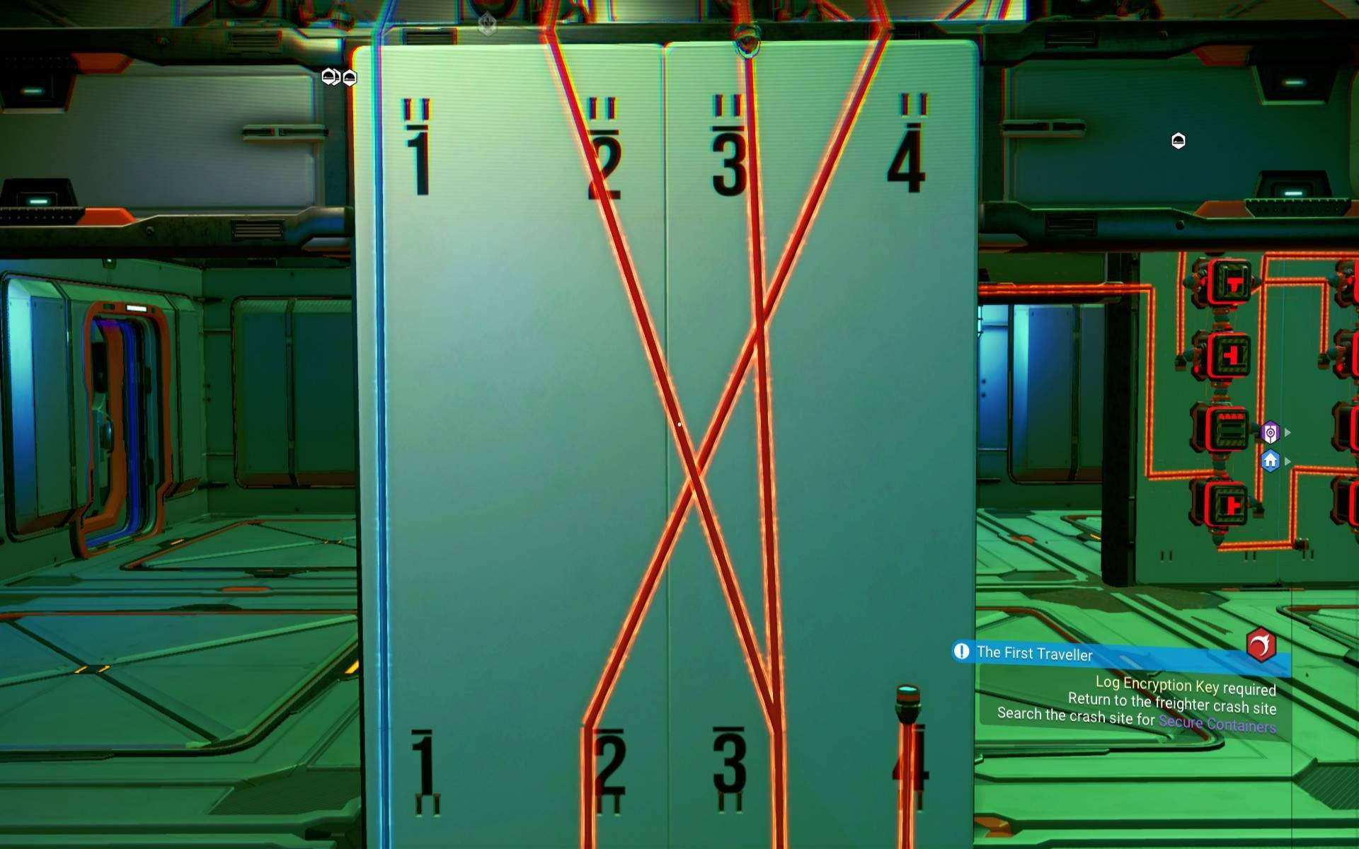
The most interesting part here is of course the PIN Code wiring that connect buttons with a locks. In my base this is exposed as a patch panel on a wall (loose cable ends on the wall, numbered with decals) so I can easily change my PIN code at any time. In the screenshot each Lock (1-4 on the top) is wired to different buttons (1-4 on the bottom), making up the PIN Code 1332.
The output part of the Switch is simply an Auto switch that opens/closes depending on the PIN Code wiring and which Lock is active at the time. Opening the Auto switch will send Power through to the signal group and enable our button.
Reset Mechanism

Because of the way the locks work, resetting the entire system is really simple. Kill the Key Signal briefly with an Invert to close all locks and the user need to start over from square one. The diagrams show how each button is connected to the Reset mechanism but this could easily be expanded with a separate button for resetting, a proximity sensor that resets the system should you walk too far away or something else.
Putting It All Together
Putting all of this together to a complete 4 digit PIN Code security system with 4 buttons to choose from would look something like this
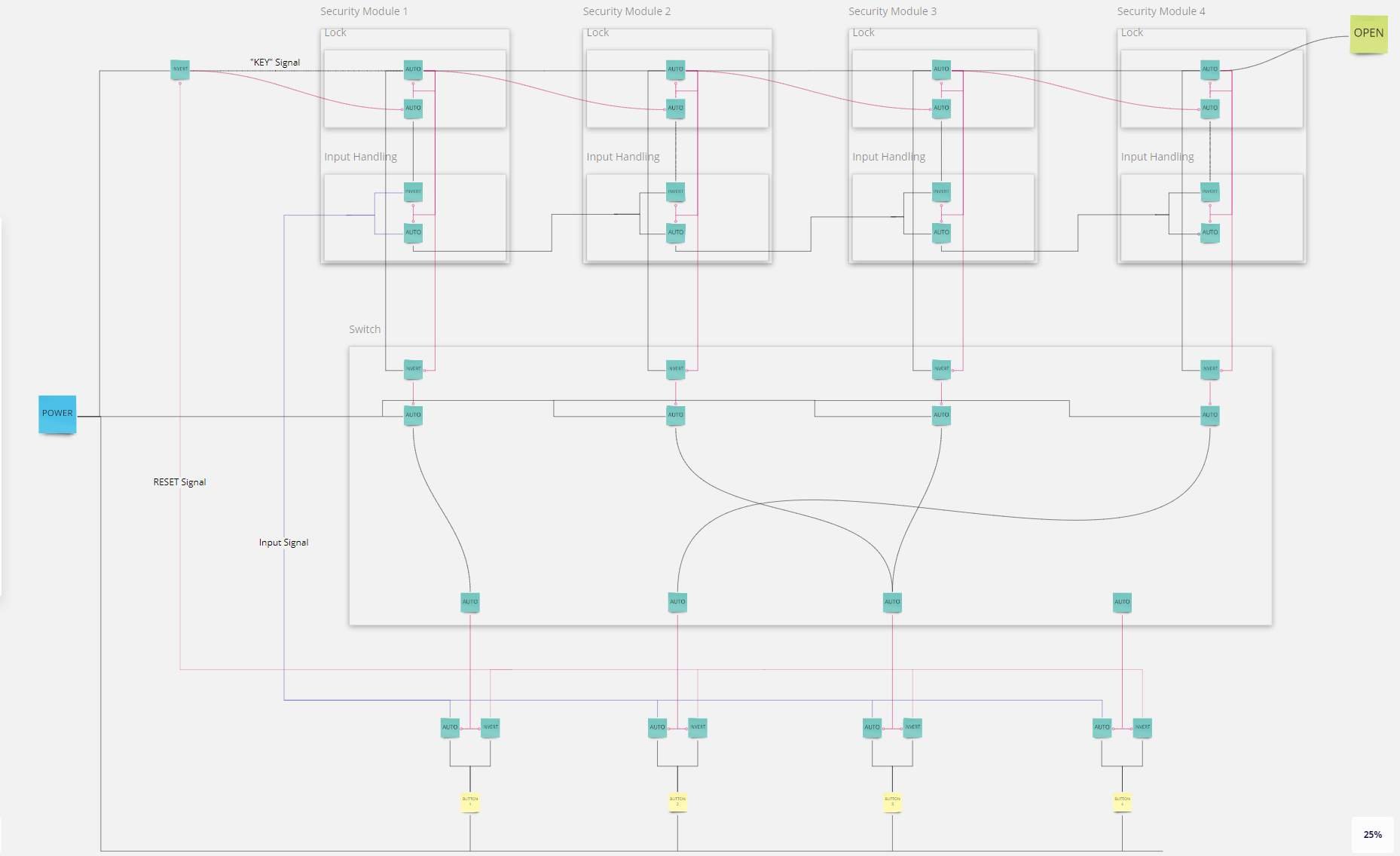
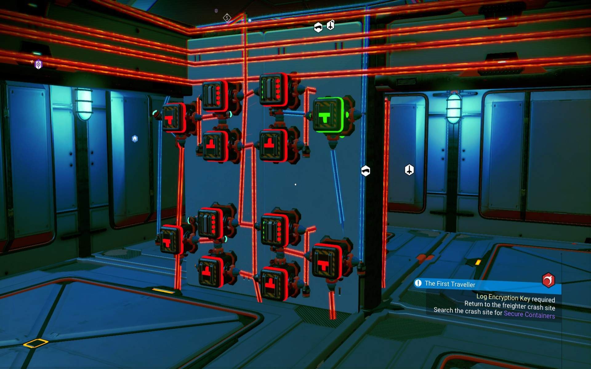
And this is what it looks like in game.
Security Module 1-4


Switch output and button selectors.
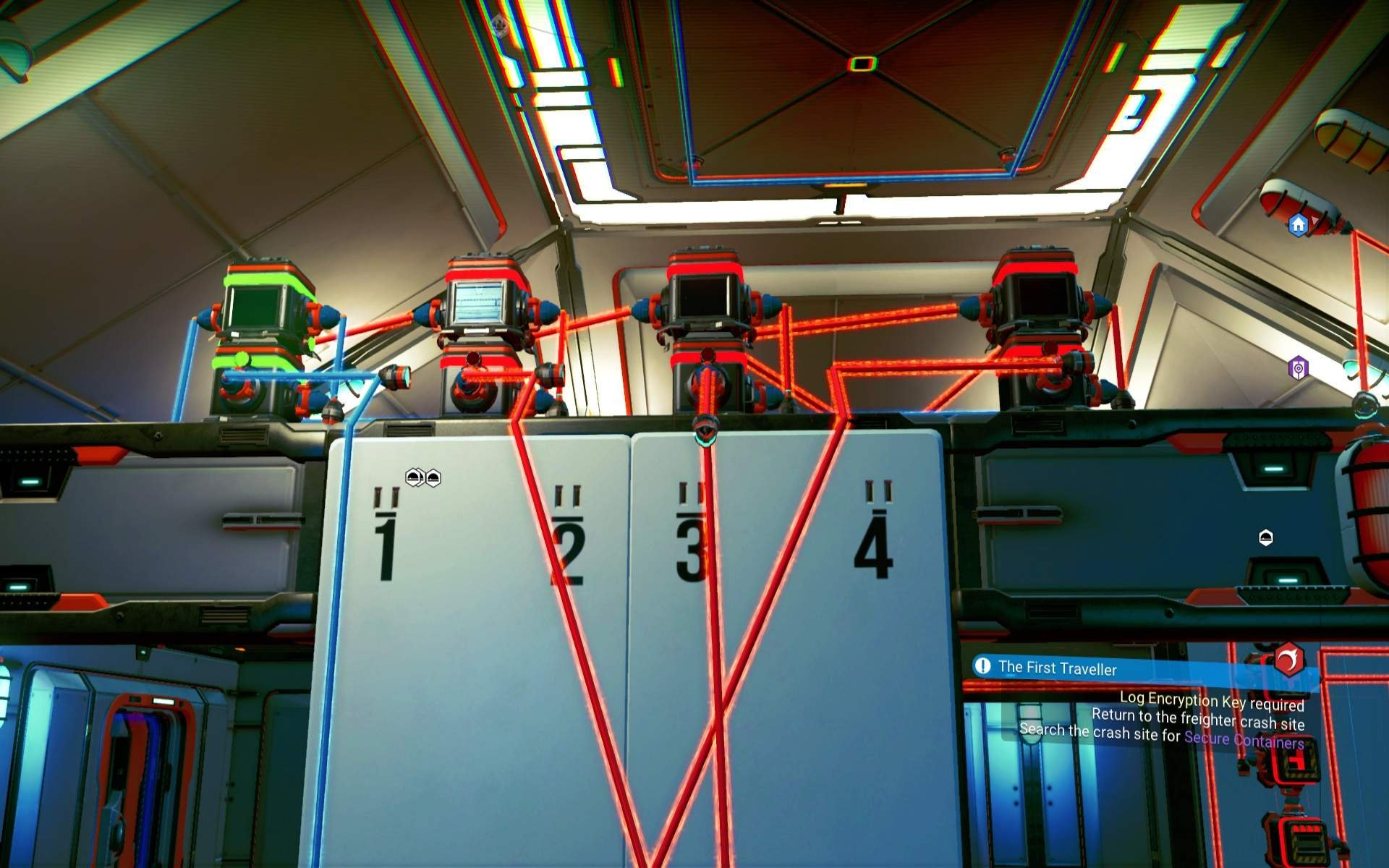
Switch input.
Known Issues
So far the only issue I’ve found is one I believe is related to how the switches work. All switches seem to have an internal clock that’s not shared with the others and signal port is only checked on each tick of that clock. So instead of opening/closing switches immediately when the incoming signal changes, they sometimes take maybe half a second or thereabouts before reacting.
This could lead to race conditions where switches go out of sync and all locks are open very quickly (due to loops) before the system has fully moved to the next stage after pressing a button (did I mention I’m not a security expert). I’d love to hear any improvements in the design that could mitigate this!
I sincerely hope this was helpful. Good luck to you!


Be the first to comment